5.13
I NDEX S E N S O R ASSEMBLY
MO U NTING SCREW
P14
p
8 • ~ 0 +
P 3 P I
PZ
QO
0o
D OOR SWITCH ASSEM B L Y
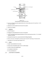
Figure 5-15
Door Switch Assembly Key Parts
5 .13.1
Re mo v a l
A. Remove the circuit board (see Section 5.3.1).
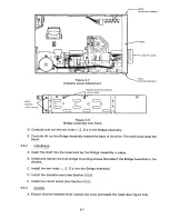
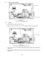
B. Gently remove the two index L. E. D. 's from the Bridge Assembly (see Figure 5-16).
P1
UPPER INDEX SENSORS
0+ ., S
P 3 P I
P2
QO
C0
TIE WRAPS
Figure 5-16
Index Sensor Assembly Key Parts, Top View
C. Turn the drive over and remove the mounting screw from the Index Sensor Assembly (see
Figure 5-17).
D. Remove the two brackets that attach the Index Sensor Assembly's wires to the chassis(see
Figure 5-16).
5-1 3
Содержание TM848-1
Страница 32: ...HUB CENTER LINE TRACK 0 TRACK 38 TRACK 76 Figure 2 2 Hub Center Line and Track Locations 2 3 ...
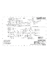
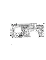
Страница 81: ...APPENDIX I PRINTED CIRCUIT BOARD S CHEM A T ICS AND ASSEM B LY DRAW IN G S ...
Страница 88: ...APPENDIX II RECOM M E N D E D SPARE PARTS LIST ...
Страница 90: ...Pi N 1 79031 001 1 082 ...

