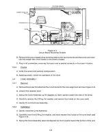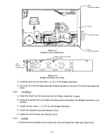
MOUNTING SCREWS
CONNECTING HEAT SINKS
POWER CONNECTOR
RETAINING CLIP
SCREW
04
0
Qo
4
Figure 5-3
Circuit Board Mounting Screws
B. Remount the circuit board using the two screws to the two heat sinks and the screw and nylon
clip that attach the circuit board to the drive's chassis.
C. Plug in all connectors, ensuring that each one is seated correctly in its proper location.
5 .3.3
Che c ks
A. Verify the select and options configuration.
B. Applying power, check the operation of the drive.
5 .4
CO NE AS S E M B L Y
5.4.1
R emova l
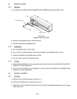
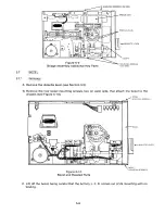
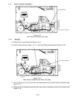
A. Remove the screw that attaches the cone bracket to the cone alignment arm (see Figure 5-4).
B. Unlatch the diskette lever.
C. Swing the Cone Assembly up 90 degrees so that it points toward the side of the drive.
D. Carefully remove the E-Ring, flat washer, and washer that holds on the cone shaft.
E. Gently lift out the Cone Assembly.
5.4.2
I ns t al l a t i o n
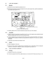
A. Gently insert the Cone Assembly.
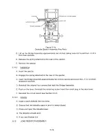
B. Carefully insert the E-Ring, flat washer, and wave washer that holds on the cone shaft (see
Figure 5-5).
C. Swing the Cone Assembly down 90 degrees so that it points toward the bottom of the unit.
5-4
Содержание TM848-1
Страница 32: ...HUB CENTER LINE TRACK 0 TRACK 38 TRACK 76 Figure 2 2 Hub Center Line and Track Locations 2 3 ...
Страница 81: ...APPENDIX I PRINTED CIRCUIT BOARD S CHEM A T ICS AND ASSEM B LY DRAW IN G S ...
Страница 88: ...APPENDIX II RECOM M E N D E D SPARE PARTS LIST ...
Страница 90: ...Pi N 1 79031 001 1 082 ...


