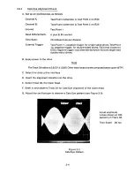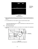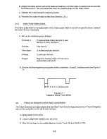
H. Verify that the smaller of the two Cats Eye lobes is not less than 75 percent in amplitude of
the other one. The calculation is:
am p o f smaller lobe
a mp o arger o e
I. Step the drive to Track 00, then, step it back to Track 38.
J. Reverify the Cats Eye pattern.
K. Step the drive to Track 76; then, step it back to Track 38.
L. Reverify the Cats Eye pattern.
M. On double-headed drives, select the upper head (Head 01) and repeat Steps F through L.
N. If any of the checks listed above does not meet the co nditions stated in Step H, the head
carriage must be adjusted.
HEAD CARRIAGE ADJUSTMENT
2.3
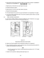
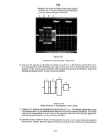
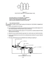
A. Turn the tw o p o s i t ion r e t aining sc rews t ha t s t r a ddle th e n y lo n a d j ustment ca m l o c a ted
beneath the drive until the cam can be moved (see Figure 2-4).
POSITION RETAINING SCREWS (2)
O
OG
)'
pop
Is-
-
0
0
'0
ADJUSTMENT CAM
Figure 2-4
Head Module Retaining
and Cam Screws
B. Observe the Cats Eye pattern from the head that is farthest out of alignment.
C. Using a flat blade screwdriver, turn the adjustment cam until one Cats Eye lobe is within 75
percent of the amplitude of the other lobe.
Note
Check the upper and lower heads on double-sided drives (see Section 2.2.1, "F" through
"L" on upper head).
D. Tighten the two positioner retaining screws (see Figure 2-4).
2-5
Содержание TM848-1
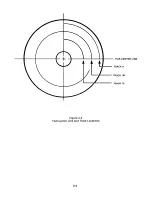
Страница 32: ...HUB CENTER LINE TRACK 0 TRACK 38 TRACK 76 Figure 2 2 Hub Center Line and Track Locations 2 3 ...
Страница 81: ...APPENDIX I PRINTED CIRCUIT BOARD S CHEM A T ICS AND ASSEM B LY DRAW IN G S ...
Страница 88: ...APPENDIX II RECOM M E N D E D SPARE PARTS LIST ...
Страница 90: ...Pi N 1 79031 001 1 082 ...


