SECTION I
INTRO D U C T IO N TO TH E T M 8 4 8 F A M ILY OF DISK DRIVES
I NTRO D U C T I O N
This section contains a description of the physical and functional specifications for the TM848-1 and-
2 disk drives, 48 tracks per inch (TPI), manufactured by Tandon Corporation.
1.1
PURPO S E O F TH E DRIVE
The drive is an eight-inch disk memory designed for random access data entry, storage, and retrieval
applications. These applications typically are intelligent terminal controllers, microcomputers, word
processing systems, data communications systems, error logging, microprogram loading, point-of-
sale terminals, and Winchester back ups.
The drive is capable of recording and reading digital data, using FM, and MFM.
PHYSICAL DESC R IPTION OF THE DRIVE
1.2
The drive can be mounted in any vertical or horizontal plane. However, when mounted horizontally,
the printed circuit board must be up.
The spindle is belt driven by a brushless D.C. motor with an integral tachometer. The servo control
circuit, suitably sized pulleys, and the tachometer control the speed of the spindle. The Read/Write,
double-sided head assembly is positioned by means of a stepper motor, split band, and a pulley.
The Read/Write/Erase head assembly is a glass-bonded manganese/zinc ceramic structure. It has a
life in excess of 20,000 hours.
For diskette loading, operator access is provide via a slot located on the front of the drive.
T he electronic components of the d rive are mo u nted on a c i r cuit board assembly located in t h e
chassis. Power and interface signals are routed through connectors that plug into the back of the drive.
1. 3
F U N C T I O N A L D E S C R IPTION OF THE DRIVE
The drive is fully self-contained. It requires no operator intervention during normal operation. The
drive consists of a spindle drive system, a head positioning system, and a read/write/erase system.
The TM848-1 is a s i n g le-sided drive. The TM8 4 8-2 is a d o u b le-sided drive. The only difference
between the two drives is the number of heads. The circuit board is identical in both models.
When the diskette lever is opened, access is provided for the insertion of a diskette. The diskette is
accurately positioned by plastic guides. The disk position is ensured by the backstop and disk ejector.
Closing the diskette lever activates the cone/clamp system, resulting in centering of the diskette and
clamping of the diskette to the drive hub. The drive hub is driven at a constant speed of 360 RPM by a
servo-controlled brushless D. C. motor. The head is loaded into contact with the recording medium
whenever the diskette lever is latched.
1-1
Содержание TM848-1
Страница 32: ...HUB CENTER LINE TRACK 0 TRACK 38 TRACK 76 Figure 2 2 Hub Center Line and Track Locations 2 3 ...
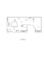
Страница 81: ...APPENDIX I PRINTED CIRCUIT BOARD S CHEM A T ICS AND ASSEM B LY DRAW IN G S ...
Страница 88: ...APPENDIX II RECOM M E N D E D SPARE PARTS LIST ...
Страница 90: ...Pi N 1 79031 001 1 082 ...


