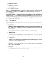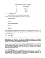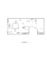
FIGURES
Figure
Number
5-1 0
5-1 'I
5-1 2
5-1 3
5-14
5-1 5
5-1 6
5-1 7
Page
Number
5-8
.. 5-9
.. 5-10
5-1 1
5-1 2
.. 5-13
5-1 3
. 5-14
5
5-1 8
et F i e r e
T i t
l e
Bezel and Related Parts
Activity L. E. D. Key Parts
Load Arm Assembly Key Parts
Track 00 Sensor Assembly Key Parts
Write Protect Sensor Assembly Key Parts. .
Door Switch Assembly Key Parts .
Index Sensor Assembly Key Parts, Top View.
Index Sensor Assembly Key Parts, Bottom View.
Diskette Ejector Assembly Key Parts
Load Resistor Assembly and Key Parts
Stepper Band Key Parts
Stepper Band Additional Key Parts
S tepper Motor Assembly Key Parts.. . . . .
Head Carriage Assembly Key Parts
TABLES
5-15
5-1 6
5-1 7
5-1 8
5-1 9
5-20
5-1 9
5-20
5-21
5-22
5-23
Table
Number
Page
Number
Title of Table
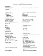
Mechanical and Electrical Specifications
Power Requirements
I nterface Connector Pin Assingments . .
Power Connector Pin Assignments
Options
Drive Interface Lines and Pin Connectors
Stepper Logic Truth Table .
1-3
1-4
1-13
1-14
1-17
3-3
3-5
1-1
1-2
1-3
1-4
1-5
3-1
3-2
Содержание TM848-1
Страница 32: ...HUB CENTER LINE TRACK 0 TRACK 38 TRACK 76 Figure 2 2 Hub Center Line and Track Locations 2 3 ...
Страница 81: ...APPENDIX I PRINTED CIRCUIT BOARD S CHEM A T ICS AND ASSEM B LY DRAW IN G S ...
Страница 88: ...APPENDIX II RECOM M E N D E D SPARE PARTS LIST ...
Страница 90: ...Pi N 1 79031 001 1 082 ...


