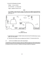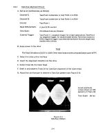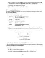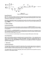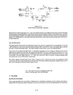
C. Connect an oscilloscope to Test Points 4 and 5, using Test Point 1 as a ground.
D. Set up an oscilloscope as follows:
Channel A:
Channel B:
Both Channels:
Test Point 4, 1 volt per division
Test Point 5, 1 volt per division
A. C. coupled, Channels A and B added,
Channel B inverted
50 milliseconds per division,
synchronize internally on Channel A or B
Automatic
Time Base:
Trigger:
E. The minimum amplitude displayed on the scope should be no less than three (3) volts peak-to-
peak at any point
F. Reverify the measurement with another work diskette.
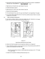
G. Check the upper and lower head, if applicable.
H. If the amplitude is less than the specification, inspect the heads to ensure they are not
contaminated.
I. Clean the heads with a cleaning diskette if they are contaminated.
J. Replace the circuit board if cleaning does not improve the amplitude.
K. If replacing the circuit board does not correct the amplitude, replace the Head Carriage
Assembly.
2 .7
AZI MUT H C H E C K
Azimuth is the angle of the heads with respect to the track at the point of the read/write gap. Azimuth is
measured in minutes (one minute
= 1/60 degree).
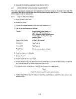
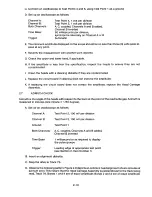
A. Set up an oscilloscope as follows:
Channel A:
Test Point 2, 100 mV per division
Channel B:
Test Point 3, 100 mV per division
Ground:
Both Channels: A. C.
coupled, Channels A and B added,
Test Point 1
Time Base:
Channel B inverted
1 miilisecond or as required to display
the pulse groups
Leading edge of appropriate test point
(see Section 2, Item Number 1)
Trigger:
B. Insert an alignment diskette.
C. Step the drive to Track 76.
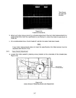
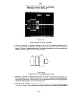
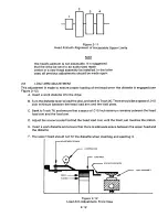
D. Observe the following pattern. Figure 2-9 depicts an optimum head alignment of zero minutes of
azimuth error. This means that the Head Carriage Assembly is perpendicular to the track being
read, Track 76. Bursts 1 and 4 are of equal amplitude; Bursts 2 and 3 are of equal amplitude.
2-10
Содержание TM848-1
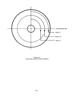
Страница 32: ...HUB CENTER LINE TRACK 0 TRACK 38 TRACK 76 Figure 2 2 Hub Center Line and Track Locations 2 3 ...
Страница 81: ...APPENDIX I PRINTED CIRCUIT BOARD S CHEM A T ICS AND ASSEM B LY DRAW IN G S ...
Страница 88: ...APPENDIX II RECOM M E N D E D SPARE PARTS LIST ...
Страница 90: ...Pi N 1 79031 001 1 082 ...


