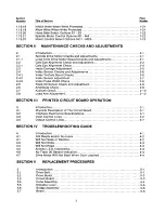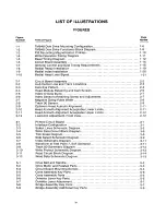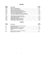
T ABLE OF CO N T E N T S
Section
Number
Page
Number
Title of Section
SECT ION I INT R O D U C T ION TO THE TM848 FAMILY OF DISK DRIVES
l.
1.1
1.2
1.3
1.4
1.5
1.6
1.7
1.8
1.9
1.10
1.10.1
1.1 0.2
1.1 0.3
1.11
1.12
1.13
1.14
1.15
1.1 5.1
1.1 5.2
1.1 5.3
1.1 5.4
1.1 5.5
1.1 6
1.1 6.1
1.1 6.2
1.17
1.1 7.1
1.1 7.2
1.1 7.3
1.18
1.19
1.1 9.1
1.1 9.2
1.1 9.3
1.1 9.4
1.1 9.5
1.1 9.6
1.1 9.7
1.1 9.8
1.1 9.9
1.1 9.1 0
1.1 9.1 1
1.1 9.1 2
1.1 9.1 3
1.1 9.1 4
1.1 9.1 5
1.1 9.1 6
1.1 9.1 7
Introduction.
Purpose Of The Drive
Physical Description of The Drive
Functional Description of The Drive
Diskettes
Mechanical and Electrical Sepcifications
Power Requirements
Interface Circuit Specifications
Incoming Inspection Checks and Procedures
Interface Connections
Mounting The Drive.
Hardware .
Dust Cover
Cooling System Requirements . . . . . . .
. . . . . . . . . . . . . . . . . . . . .
Diskette Care, Handling and Storage .
Write Protect.
O peration of The Drive . . . . .
Organization of The Drive
Components of The Drive
Index Pulse
Drive Status Logic .
Spindle Drive System
Positioner Control
Data Electronics
Interface Electronics
Interface Connector Pin Assignments, P13.
Power Connector Pin Assignments
Terminated Lines .
Input Line Terminations From Removable Resistor Pack .
Drive Select.
Program Shunt .
DS and HL Power Save Options
User-Selectable Options ..
D rive Select DS1- D S 4 .
S ide Select Options Using Drive Select 1B - 4 B .
In Use From Drive Select .
I n Use From Head Load . .
Ready Alternate Output Pad
Radial Ready
Ready Modified .
Radial Index
Index Alternate Output Pad
In Use Altenate Output Pad
Diskette Lever Lock Latch Option
Disk Change
Two-Sided Diskette Installed.
Stepper Power From Drive Select
Stepper Power From Head Load Line
Head Load Alternate Output Pad Option
R adial Head Load Signal Option .
. 1-1
. 1-1
. 1-1
. 1-1
. 1-2
I-2
. 1-2
. 1-2
. 1-2
1-5
. 1-5
. 1-6
. 1-6
.. 1-6
1-6
1-7
1-7
1-7
1-7
1-8
1-8
1-9
1-9
1-9
1-12
1-12
1-12
1-14
1-14
1-14
.. 1-14
1-17
1-1 7
1-18
1-18
1-18
1-18
1-18
1-1 9
. 1-19
1-1 9
1-20
1-20
1-20
1-20
1-20
1-21
1-21
1-21
1-21
Содержание TM848-1
Страница 32: ...HUB CENTER LINE TRACK 0 TRACK 38 TRACK 76 Figure 2 2 Hub Center Line and Track Locations 2 3 ...
Страница 81: ...APPENDIX I PRINTED CIRCUIT BOARD S CHEM A T ICS AND ASSEM B LY DRAW IN G S ...
Страница 88: ...APPENDIX II RECOM M E N D E D SPARE PARTS LIST ...
Страница 90: ...Pi N 1 79031 001 1 082 ...


