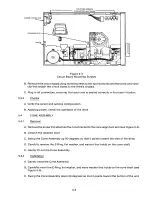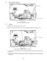
E. Cut the tie wraps along the cable harness (see Figure 5-16).
F. Lift out the Index Sensor Assembly (P1).
TIE BRACKETS, 2 FAR SIDE
TIE BRACKET, I NEAR SIDE
0
0
0
0
0
0
L OWER INDEX SENSOR ASSEM B L Y
(60I
MOUNTING SCREW
Q
Atoll i<A4 MNI SIIIII
@
0
Figure 5-17
Index Sensor Assembly Key Parts, Bottom View
5.13.2
Ins t a l l a t io n
A. Put the Index Sensor Assembly into the drive.
B. Loop the wires to the cable harness and chassis.
C. Insert the two L. E. D. index sensors into their sockets.
D. Using the original mounting screw, attach the index L. E. D. to the drive's chassis.
E. Cable harness the bundle of wires, including the Index Sensor Assembly's wires.
F. Reinstall the circuit board (see Section 5.3.2).
5 .13.3
Chec k s
A. Check the index-to-data adjustment (see Section II).
DISKETTE EJECTOR ASSEMBLY
5.1 4
5 .14.1
Re m o v a l
A. Remove the circuit board (see Section 5.3.1).
B. Remove the door lock lever (see Figure 5-6).
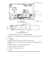
C. Locate and remove the four screws, two on each side, that hold the Bridge Assembly (see
Figure 5-7).
5-1 4
Содержание TM848-1
Страница 32: ...HUB CENTER LINE TRACK 0 TRACK 38 TRACK 76 Figure 2 2 Hub Center Line and Track Locations 2 3 ...
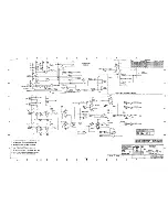
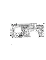
Страница 81: ...APPENDIX I PRINTED CIRCUIT BOARD S CHEM A T ICS AND ASSEM B LY DRAW IN G S ...
Страница 88: ...APPENDIX II RECOM M E N D E D SPARE PARTS LIST ...
Страница 90: ...Pi N 1 79031 001 1 082 ...


