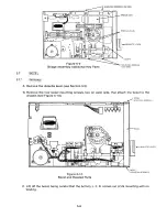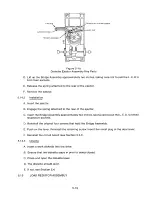
MO U NTING SCREWS, 3 PLACES
STEPPER MOTOR ASSEMBLY
0
4
o
Q
Qo
0
O
Qo
0
0
(> 0
Figure 5-21
Stepper Band Additional Key Parts
5.17
STEPP E R M O TOR ASSEMBLY
5 .17.1
Re m o v a l
It is suggested that the drive be returned to an authorized Tandon repair center when removing the
Stepper Motor Assembly.
A. Remove the circuit board (see Section 5.3.1).
B. Remove the stepper band (see Section 5.16.1).
C. Remove the three mounting screws that attach the Stepper Motor Assembly to the chassis
(see Figure 5-2 2).
D. Remove plug connectors P4 and P5 from the circuit board.
E. Cut the tie wraps that connect the stepper motor wires to the load resistors.
F. Lift out the Stepper Motor Assembly.
Note
Be careful not to damage the stepper band.
5.17.2
I ns t a l l a t ion
A. Place the Stepper Motor Assembly into the drive's chassis.
B. Using the original three mounting screws, attach the Stepper Motor Assembly to the chassis.
5-1 8
Содержание TM848-1
Страница 32: ...HUB CENTER LINE TRACK 0 TRACK 38 TRACK 76 Figure 2 2 Hub Center Line and Track Locations 2 3 ...
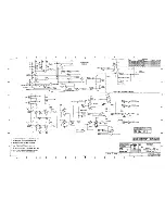
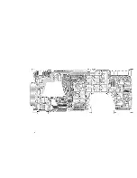
Страница 81: ...APPENDIX I PRINTED CIRCUIT BOARD S CHEM A T ICS AND ASSEM B LY DRAW IN G S ...
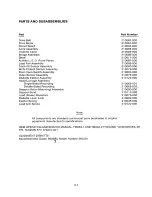
Страница 88: ...APPENDIX II RECOM M E N D E D SPARE PARTS LIST ...
Страница 90: ...Pi N 1 79031 001 1 082 ...

