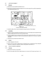
CONE BRACKET
SCREW
CONE ALIGNMENT ARM
E-RING A WASHER
WAVE WASHER
DISKETTE LEVER
0
p
Qo
CONE ASSY
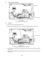
Figure 5-4
Cone Assembly Key Parts
D. Latch the diskette lever.
E. Insert the screw that attaches the cone bracket to the cone alignment arm(see Figure 5-5).
E-RING
FLAT WASHER
WAVE WASHER
CONE BRACKET
FLAT WASHER (2)
CONE ASSEMBLY
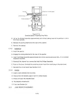
Figure 5-5
Cone Assembly Parts
5.4.3
Chec ks
A. Ensure that the Cone Assembly turns freely.
B. If not, reverify that the Cone Assembly has been installed correctly.
C. Insert a diskette.
D. Ensure that the diskette is clamped properly by the cone.
5-5
Содержание TM848-1
Страница 32: ...HUB CENTER LINE TRACK 0 TRACK 38 TRACK 76 Figure 2 2 Hub Center Line and Track Locations 2 3 ...
Страница 81: ...APPENDIX I PRINTED CIRCUIT BOARD S CHEM A T ICS AND ASSEM B LY DRAW IN G S ...
Страница 88: ...APPENDIX II RECOM M E N D E D SPARE PARTS LIST ...
Страница 90: ...Pi N 1 79031 001 1 082 ...

