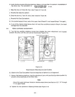
B. Adjust the index sensor with a flat blade screwdriver until the index-to-data burst occurs 200
micros 100 microseconds from the leading edge of the index pulse.
C. Tighten the index sensor's retaining screw.
D. Reverify the index-to-data bursts (see Section 2.3.1).
2.4.3
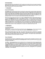
Index P u l s e Width Check
The index pulse width is nonadjustable. If the index pulse width is not within specifications, replace
the Index Sensor Assembly.
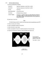
A. Set up an oscilloscope as follows:
Channel A:
Ground:
To appropriate index test point, see
Section 2, Item Number 1.
Test Point 1
.5 millisecond per division
2 volts per division
Negative leading edge of Channel A,
appropriate test point.
Time Base:
Voltage:
Trigger:
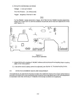
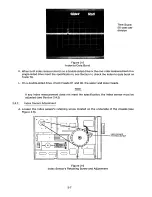
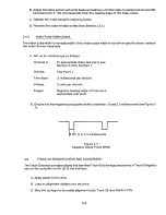
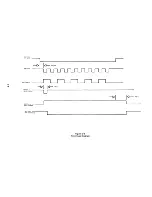
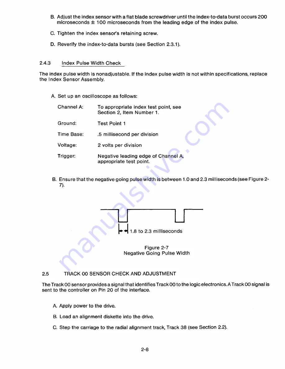
B. Ensure that the negative going pulse width is between 1.0 and 2.3 milliseconds(see Figure 2-
7).
1.8 to 2.3 milliseconds
Figure 2-7
Negative Going Pulse Width
2.5
TRACK 0 0 S E N SOR CHECK AND ADJUSTMENT
The Track 00 sensor provides a signal that identifies Track 00 to the logic electronics. A Track 00 signal is
sent to the controller on Pin 20 of the interface.
A. Apply power to the drive.
B. Load an alignment diskette into the drive.
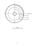
C. Step the carriage to the radial alignment track, Track 38 (see Section 2.2).
2-8
Содержание TM848-1
Страница 32: ...HUB CENTER LINE TRACK 0 TRACK 38 TRACK 76 Figure 2 2 Hub Center Line and Track Locations 2 3 ...
Страница 81: ...APPENDIX I PRINTED CIRCUIT BOARD S CHEM A T ICS AND ASSEM B LY DRAW IN G S ...
Страница 88: ...APPENDIX II RECOM M E N D E D SPARE PARTS LIST ...
Страница 90: ...Pi N 1 79031 001 1 082 ...


