Note
This option does not stop the write protect signal from being sent on the interface line.
This option is implemented by cutting WP, and by installing NP.
1.19.20 H ead Side Select Options S1-83
This option allows heads to be selected by side select, drive select, or the direction control signal. The
drive comes with side select, S2, installed.
To use the drive select line to enable the heads, cut S2 and install S3 along with the proper 1B-4B
jumper that is used with S3 (see 1B-4B). For head selection using Direction Select, cut S2, and install
S1.
1 .19.21 S p i n d l e M o tor Control Options M 1 - M 4
M1 is used to e n a ble the m o tor off de lay timer. When this jumper is installed, the drive motor is
enabled and disabled by either the drive select (M3) or head load (M4) commands. A 20-second turn
turn off delay of the spindle motor is activated on the trailing edge of the controlling signal.
M2 is used for radial motor control independent of the motor control functions installed with M1, M3,
and M4.
M2 should be in if the user wishes to enable the drive motor continuously or to use the radial motor on
line MC1-MC4.
M3 is used to control the drive motor using drive select. When the drive select line goes low (true), the
drive motor comes up to speed in less then 500 milliseconds and becomes ready in less than 700
milliseconds. After the d r ive se lect l ine g oe s f a lse (high), the mo tor w ill run fo r 2 0 s e c o n ds. To
implement this option, install a jumper at location M3. For correct operation of M3, remove M4.
M4 is used to start the drive motor using the head load interface lines. When the head load line goes
low (true), the drive motor comes up to speed in less than 500 milliseconds and becomes ready in less
than 700 milliseconds. After the head load line goes high (false), the motor will run for 20 seconds. To
implement this option, remove M3 for correct operation of option M4.
1.19.22
M ot o r C o n t r ol Select Options MC1 - M C 4
This option is used if the drive motor is to be enabled independent of drive select or head select. When
these lines are low (t rue), the motor is off. The drive comes without this option installed. This option
does not operate the time out delay circuit.
To implement this option that controls the drive motor using an MCx line, install the appropriate MC1-
MC4 jumper. When using this option, M2 must be installed. If the motor turn off delay is desired, the
delay can be triggered by Drive Select or Head Load commands, when used in conjunction with M3 or
M4.
1-22
Содержание TM848-1
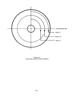
Страница 32: ...HUB CENTER LINE TRACK 0 TRACK 38 TRACK 76 Figure 2 2 Hub Center Line and Track Locations 2 3 ...
Страница 81: ...APPENDIX I PRINTED CIRCUIT BOARD S CHEM A T ICS AND ASSEM B LY DRAW IN G S ...
Страница 88: ...APPENDIX II RECOM M E N D E D SPARE PARTS LIST ...
Страница 90: ...Pi N 1 79031 001 1 082 ...

