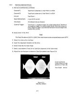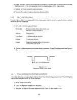
D. Confirm the position by observing the Cats Eye pattern.
E. Attach Channel A to Test Point 10.
F. Restore the carriage to Track 00, and ensure that the Track 00 L. E. D. on the exerciser turnson.
G. Seek to Track 1, and ensure that the signal at Test Point 10 is high.
H. Seek to Track 2, and ensure that this line is low or in transition.
I. Seek to Track 3, and ensure that this line is low.
J. If the signal is incorrect, restore to Track 00 with the oscilloscope attached as above.
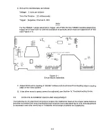
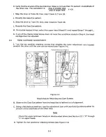
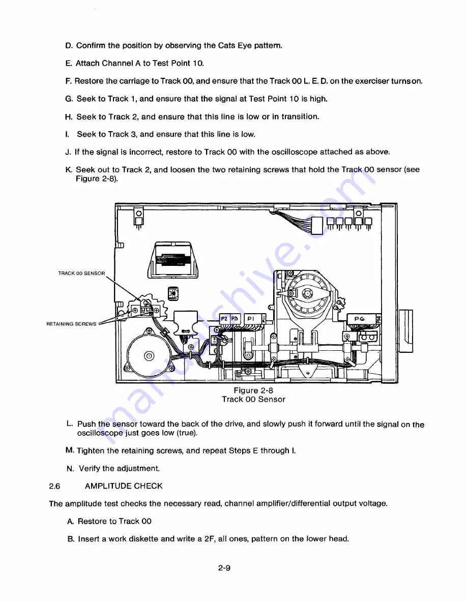
K. Seek out to Track 2, and loosen the two retaining screws that hold the Track 00 sensor (see
Figure 2-8).
TRACK 00 SENSOR
+
I
P2 PS
Pl
RETAINING SCREWS
0o
Figure 2-8
Track 00 Sensor
L P ush the sensor toward the back of the drive, and slowly push it forward until the signal on the
oscilloscope just goes low (true).
M. Tighten the retaining screws, and repeat Steps E through I.
N. Verify the adjustment.
AMPLITUDE CHECK
2.6
The amplitude test checks the necessary read, channel amplifier/differential output voltage.
A. Restore to Track 00
B. Insert a work diskette and write a 2F, all ones, pattern on the lower head.
2-9
Содержание TM848-1
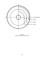
Страница 32: ...HUB CENTER LINE TRACK 0 TRACK 38 TRACK 76 Figure 2 2 Hub Center Line and Track Locations 2 3 ...
Страница 81: ...APPENDIX I PRINTED CIRCUIT BOARD S CHEM A T ICS AND ASSEM B LY DRAW IN G S ...
Страница 88: ...APPENDIX II RECOM M E N D E D SPARE PARTS LIST ...
Страница 90: ...Pi N 1 79031 001 1 082 ...


