BEZEL
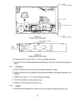
MO U NTING SCREWS, 2
BEZEL
~
DISKE T T E LEVER
0
p
Qo
BEZEL
MO U N TNG SCREWS. 2
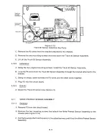
Figure 5-7
Diskette Lever Adjustment
BRIDGE MOUNTING SCREW S
2 BOTH SIDES
0o
o
o
BEZEL
SCREWS
2 BOTH SIDES
0
0
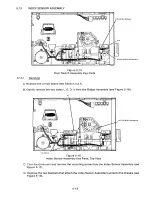
Figure 5-8
Bridge Assembly Key Parts
D. Carefully pull out the two index L. E. D.'s in the Bridge Assembly.
E. Carefully lift out the Bridge Assembly toward the back of the drive. The shaft must clear the
bezel.
Installation
5.6.2
A. Insert the shaft into the bezel and lay the Bridge Assembly in place.
B. Install and tighten the four bridge mounting screws that attach the Bridge Assembly to the
chassis.
C. Install the two index L . E. D.'s into the Bridge Assembly.
D. Install the diskette lever (see Section 5.5.2).
E. Install the circuit board (see Section 5.3.2).
5.6.3
Checks
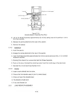
A. Ensure that the diskette lever clamps the cone and loads the head (see Figure 5-9).
5-7
Содержание TM848-1
Страница 32: ...HUB CENTER LINE TRACK 0 TRACK 38 TRACK 76 Figure 2 2 Hub Center Line and Track Locations 2 3 ...
Страница 81: ...APPENDIX I PRINTED CIRCUIT BOARD S CHEM A T ICS AND ASSEM B LY DRAW IN G S ...
Страница 88: ...APPENDIX II RECOM M E N D E D SPARE PARTS LIST ...
Страница 90: ...Pi N 1 79031 001 1 082 ...

