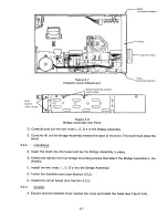
P6
0
p
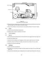
DRIVE
MOTOR
Oo
0o
MO U NTING SCREW S
(3 PLACES)
TIE WRAPS
(12 PLACES)
DRIVE MOTOR WIRES
Figure 5-2
Drive Motor and Related Parts
C. Carefully rebundle the wires, including the drive motor wire, and cable harness them (see
Figure 5-2).
D. Plug P6 into the circuit board.
E. Turn the drive over, and reinstall the drive belt (see Section 5.1.2).
5.2.3
C hec k s
A. Check to ensure that the drive motor works.
B. Check the spindle speed (see Section II).
5 .3
CI RCU I T B O A R D
5.3.1
R emo va l
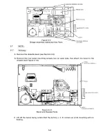
A. Remove all the connectors from the circuit board.
B. Remove the two side mounting screws that connect the two regulator heat sinks to the drive's
chassis (see Figure 5-3).
C. Remove the screw and the retaining clip that attach the circuit board to the dirve's chassis.
D. Lift the circuit board away from the drive.
E. Remove the power connector by pushing down on its top. Lift its wires out, using the slot
provided (see Figure 5-3).
Installation
5.3.2
A . Install the p o we r c o n n e c tor b y r e t h reading th e p o we r w i res an d p u s h ing i n t h e p o w e r
connector from the back of the drive.
5-3
Содержание TM848-1
Страница 32: ...HUB CENTER LINE TRACK 0 TRACK 38 TRACK 76 Figure 2 2 Hub Center Line and Track Locations 2 3 ...
Страница 81: ...APPENDIX I PRINTED CIRCUIT BOARD S CHEM A T ICS AND ASSEM B LY DRAW IN G S ...
Страница 88: ...APPENDIX II RECOM M E N D E D SPARE PARTS LIST ...
Страница 90: ...Pi N 1 79031 001 1 082 ...

