It is recommended that the interface cable be flat ribbon cable, with a characteristic impedance of
100 ohms.
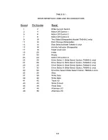
Interface connector pin assignments are given in Table 3-1.
3.3
IN P U T C O N T R O L LINES
A. DS1-DS4, Select Lines
Functional Description
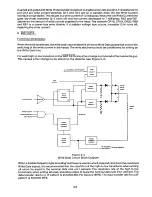
The select lines (see Figure 3-3) provide a means of selecting and deselecting a drive. These four
lines, DS1 through DS4, select one of the four drives attached to the controller. When the signal logic
level is true (low), the drive electronics are activated, and the drive is conditioned to respond to Step or
Read/Write commands. When the logic level is false (high), the input control lines and output status
lines are disabled.
IBD
R4
IOK.
RB
Dz I
DSI
BIRD "
04
D 52 2 5
EK3 30
05a ~32
ZB
4 0 7
$
4.7~ F"
504
LSDO
DS
US Qz
+SV
IZ
U I
READ
LOAD
SDLELIOIO
Ul
150
DIN+
9 O
5
( All 3 4
LSI4
r 1
150
L502.
U5
+ JV
l4
l4
4 QS
504
2
V3
4 - . I
Ql
4
5 00
I'5
RVB
100
+5V
ISD
V3I
B Q 4
2
L'304
3
BLUFF -
NLL
5
0
.
' X Q 5
c
Fa
I
2
5 READ lOAD
FR EO
2 D
Q
UEQ
U2'5
+24~
2 754EIB,
I
I
33LENDIO
Vl
LEVER
IDES
D~R~
a
DL
«I
— 5
NLOFF -
Q
NERO IDRDI
lFVERUXK LATCNE
3
UC
L500
2
IJ I 5
lK
(
27
35
142.
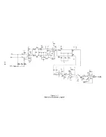
Figure 3-3
Select Lines Schematic Diagram
A select line must remain stable in the true (low) state until after a Step or Read/Write command has
been executed.
The drive select address (1-4) is determined by shorting plugs on the circuit board. Select lines 1
through 4 provide a means of daisy chaining a maximum of four drives to a controller. Only one line
can be true (low) at a time. An undefined operation might result if two or more units are assigned the
same address or if two or more select lines are in the true (low) state simultaneously.
Circuit Description
An 150-ohm resistor holds the output of the appropriate Select line high (false) until the line is driven
low(true). Then, the Select signal is gated through U1 and U5 to derive the signal DRSEL+. DRSEL+
is used to gate all I/O Port, ensuring that only one drive's data is present on the interface at a time.
Writing and ste pping are also gated by the s ig nal DRSEL+. This signal is inverted by U 13, then
buffered by U15 to drive the Activity L. E. D., which is located on the front panel. Option Z is factory
installed. It should be installed for the Activity L. E. D. to operate with Drive Select.
B. MOTOR ON, Drive Motor Enable
3-2
Содержание TM848-1
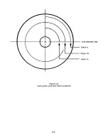
Страница 32: ...HUB CENTER LINE TRACK 0 TRACK 38 TRACK 76 Figure 2 2 Hub Center Line and Track Locations 2 3 ...
Страница 81: ...APPENDIX I PRINTED CIRCUIT BOARD S CHEM A T ICS AND ASSEM B LY DRAW IN G S ...
Страница 88: ...APPENDIX II RECOM M E N D E D SPARE PARTS LIST ...
Страница 90: ...Pi N 1 79031 001 1 082 ...

