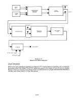
Functional Description
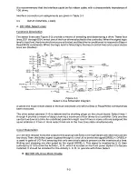
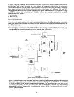
The TM848 has a D. C. brushless motor that can be enabled in three ways:
1. By using the four radial Motor Control lines, MC1 through MC4.
2. By the Head Load line using shorting plug M4. Using this line enables all drives' Motor On
lines.
3. By Drive Select, using shorting plug M3.
The Motor Control lines, MC1 through MC4, are true (low) signals that turn the motor off. Shorting plug
M2 must be installed for these control lines to operate.
When a Motor Control line is false (high), the drive motor accelerates to its operational speed in less
then 500 milliseconds. This keeps the spindle rotating at a constant speed of 360 RPM. When the
Motor Control line is true (low) the motor coasts to a stop.
When using Head Load to enable the drive motor, M4 must be installed. All of the motors are enabled
when the Head Load line goes true (low). M1 should be installed if a motor turn off delay is desired.
See Section 1.19.21 for an additional description of this circuit.
When a Drive Select line is to be used for Motor Enable, M3 must be installed. This enables the drive
motor when the Select line goes low.
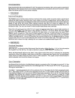
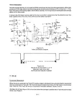
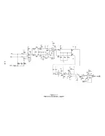
Circuit Description
When the motor is enabled by any of the above, U35, Pin 6, floats high, allowing the speed control U41
to start the drive motor. Two Hall Effect transducers in the motor, supply the necessary feedback
signals for proper speed regulation. When U35-6 goes high, the output of U41, Pin 6, turns on Q21,
which in turn applies a varying voltage to Q20 that regulates the amount of current through Q20, and
the motor driver transistors Q1 through Q4. Transistors Q1 through Q4 are turned on by the gated
pulses derived from the conditioned outputs of the Hall Effect transducers. The conditioned output of
U38, Pin2, is subsequently conditioned by Gate U36, which acts as an edge trigger and pulse doubler.
This signal is fed back to U41, Pins 2 and 3, which results in closed loop speed control. The drive
motor's rotational speed is approximately 2520 RPM, when adjusted, to give a spindle speed of 360
RPM.
C. DIR STEP, Direction and Step Lines
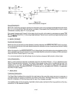
Functional Description
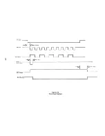
When the drive is selected, a true (low) pulse with a time duration between 200 nanoseconds and 2
milliseconds on the Step line initiates the track access motion. The direction of motion is determined
by the logic state of the Direction line when a Step pulse is issued. The motion is toward the center of
the drive if the Direction line is in the true (low) state when a Step pulse is issued. The direction of
motion is away from the center of the drive if the Direction line is in the false (high) state when a Step
pulse is issued. To ensure proper positioning, the Direction line should be stable for a minimum of 100
microseconds before the trailing edge of the corresponding Step pulse. The Direction line should
also remain stable until 100 microseconds after the trailing edge of the Step pulse. The access
motion is initiated on the trailing edge of the Step pulse.
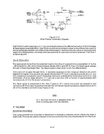
When the carriage is positioned at Track 00 and the stepper motor is at Phase 0, the signal at Pin 42 of
P13 goes true (low), indicating that Track 00 has been reached.
When stepping in or out, Test Point 8 is a high going pulse for each step pulse issued.
3-4
Содержание TM848-1
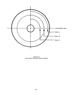
Страница 32: ...HUB CENTER LINE TRACK 0 TRACK 38 TRACK 76 Figure 2 2 Hub Center Line and Track Locations 2 3 ...
Страница 81: ...APPENDIX I PRINTED CIRCUIT BOARD S CHEM A T ICS AND ASSEM B LY DRAW IN G S ...
Страница 88: ...APPENDIX II RECOM M E N D E D SPARE PARTS LIST ...
Страница 90: ...Pi N 1 79031 001 1 082 ...

