1.19.14 St epper Power From Drive Select (DS)
This option allows the user to remove D. C. power from the stepper motor using drive select, which
results in lower stand-by current consumption.
The Stepper Power From Drive Select option is implemented by installing DS, and cutting HL.
1.19.15 S t epper Power From Head Load Line (HL)
This option supplies power to the stepper motor when the head load line goes low(true). This results
in lower stand-by current consumption.
This option is factory installed. DS must be removed for proper operation.
1.19.16
H e a d L o a d Alternate Output Pad Option C
This option allows the user to load and unload the head load solenoid (optional) and, along with the HL
and Y options, enables the stepper motor and lights the Activity L. E. D., respectively. Head load is
a ccomplished by connecting both option pads C located near interface connecto r P 1 3 .
1.19.17
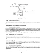
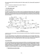
R a d i a l Head Load Signal, Options A, B, and X
By selection of the appropriate combination of the A, B, or X jumper, the user can use either Drive
Select or Head Load to activate the Activity L. E. D. and Lever Lock Solenoid option (see Figure 1-10).
R4
Dsl
DSI
2 1
IB
052 2 S
Clss 30
Dsa [~P
D'SZ
4
L'S04
35
ZB
DS'S
054
+C7
$
4.7VIP
L'300
Ul
N l
1 5
US QZ
at,
STRE OI +
HEAD
LOAD
SOLELIOID
to
Ul
2
14
12,
9
5
D lit +
SIDE
l'314
Dl I
LSDZ
U5
L'304
VIS
A Cls
US
I
- . I
4 L S D D
15
295
2
100
Ol
ACTH/ITT
14
14
U'\
ls 5
rl
4
LS04
3
HLOFF -
HLL
4
5
LSDB
I
IS HEAD LEAD
F.R lzl
2 D
Q
+Z4
79
UICo
2
U 2'S
Ulo
2 754Co?.
SOENDIO
N IOFF -
HEAD IDADI
lEVER IOCK LATCHl
0
2-
UC
(
L DO
U15
27
IK
lCiAZ,
Figure 1-10
Radial Head Load Signal
1.19.18 I n h i b it Write When Write Protected (WP)
This option is used to lock out the write gate when a write protected diskette is installed.
Inhibit Write When Write Protected is factory installed.
1.19.19 A l l o w W r ite When Write Protected (NP)
This option allows the controller to write on any diskette, whether or not is is write protected.
1-21
Содержание TM848-1
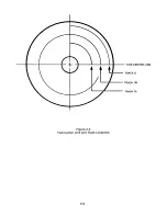
Страница 32: ...HUB CENTER LINE TRACK 0 TRACK 38 TRACK 76 Figure 2 2 Hub Center Line and Track Locations 2 3 ...
Страница 81: ...APPENDIX I PRINTED CIRCUIT BOARD S CHEM A T ICS AND ASSEM B LY DRAW IN G S ...
Страница 88: ...APPENDIX II RECOM M E N D E D SPARE PARTS LIST ...
Страница 90: ...Pi N 1 79031 001 1 082 ...

