5 .9
LOA D A R M A S S E M B L Y
5.9.1
R emov a l
A. Remove the circuit board (see Section 5.3.1).
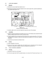
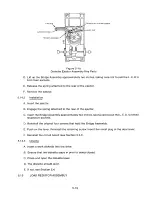
B. Remove the mounting screw and washer that are used to attach the Load Arm Assembly to
the chassis (see Figure 5-12).
0+
llfllflflIIIJIIII
0
0
po
LOAD ARM
REAR
MO U N TING SCREW, WASHER, AND SPRING
Figure 5-12
Load Arm A
ssembly Key Parts
C. Carefully slide out the Load Arm A
ssembly
toward the rear of the chassis.
5 .9.2
I nst a l l a t i o n
A. Slide the Load Arm Assembly into position from the rear of the chassis, ensuring that the load
spring is sitting under the front of the mounting screw.
B. Install and tighten the mounting screw that attaches the Load Arm Assembly to the chassis,
ensuring that the washer is under the screw and that the head lift arm is over the Load Arm
Assembly.
C. Install the circuit board (see Section 5.3.2).
5 .9.3
Chec k s
A. Insert a diskette in the drive.
B. Ensure that th e h ea d i s l o a ded w he n th e d i s kette fever is a c t ivated and t hat a d e q uate
clearance is attained for diskette insertion and ejection (see Section II).
5.10
TRAC K 0 0 S E N SOR ASSEMBLY
5.10.1 Removal
A. Remove P2 from the circuit board.
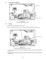
B. Cut the tie wraps that hold the cable harness, and remove the P2 wires (see Figure 5-13).
5-10
Содержание TM848-1
Страница 32: ...HUB CENTER LINE TRACK 0 TRACK 38 TRACK 76 Figure 2 2 Hub Center Line and Track Locations 2 3 ...
Страница 81: ...APPENDIX I PRINTED CIRCUIT BOARD S CHEM A T ICS AND ASSEM B LY DRAW IN G S ...
Страница 88: ...APPENDIX II RECOM M E N D E D SPARE PARTS LIST ...
Страница 90: ...Pi N 1 79031 001 1 082 ...

