


4-4
Operating the Converter
590+ Series DC Digital Converter
Setting-up the Converter
The following start-up routine assumes that the Operator Station is fitted and is in default mode,
and that the Converter’s control terminals are wired as shown in the Minimum Connection
diagrams in Chapter 3.
The following instructions are written in logical order. Complete each stage successfully
before progressing to the next.
Calibrating the Control Board
AUXILIARY POWER ONLY IS CONNECTED AT THIS STAGE
You must first calibrate the Converter for use with the motor.
Connect the auxiliary power supply to auxiliary supply terminals L &
N (Frame 3: Terminals L & N = D8 & D7), but do not connect the
main 3-phase power supply at this stage. Check that the correct voltage
appears between these terminals.
The Operator Station will now display the Welcome screen, and the
Health and Overcurrent Trip Operator Station LEDs will be illuminated
(assuming that the Converter’s control terminals are wired as shown in
Figure 3-4, Minimum Connection Requirements).
Note:
The CONFIGURE DRIVE menu at the top of the menu tree contains
many of the important parameters used during set-up.
Refer to Chapter 5: “The Operator Station” to familiarise yourself
with the Operator Station’s LED indications, and how to use the
keys and menu structure.
IMPORTANT:
You must not exceed the maximum drive and motor ratings. Refer to the Product Code or
maximum rating label, and the motor rating plate.
Set the following parameters:
CONFIGURE ENABLE
Set to ENABLED. This allows you to change parameter values, but the drive cannot run.
NOM MOTOR VOLTS – Armature Voltage (VACAL)
If the drive is designed for use on a nominal 3-phase power supply of 220V, set DOUBLE the
Armature Voltage value in the NOM MOTOR VOLTS parameter.
OR
If the drive is designed for use on a nominal 3-phase power supply of 500, 600 or 690V, set the
Armature Voltage value in the NOM MOTOR VOLTS parameter.
Note:
Refer to the Product Code on the drive's Rating Label to confirm the drive's specification.
Also refer to Chapter 2: "An Overview of the Drive" - Understanding the Product Code.
ARMATURE CURRENT (IA CAL)
Note the maximum armature current from the motor rating plate and set this value in the
ARMATURE CURRENT parameter.
FIELD CURRENT (IF CAL)
Note the nominal field current from the motor rating plate and set this value in the FIELD
CURRENT parameter.
Frame H:
The factory setting of the power board calibration switches allows for a Field Current
range of up to 20A. If the Field Current is greater than 20A, refer to Chapter 7: "Trips and Fault
Finding" - Current Calibration Switches (Frame H).
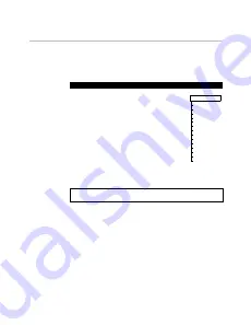
MMI Menu Map
1
CONFIGURE DRIVE
CONFIGURE ENABLE
NOM MOTOR VOLTS
ARMATURE CURRENT
FIELD CURRENT
FLD.CTRL MODE
FLD.VOLTS RATIO
CUR.LIMIT/SCALER
AUTOTUNE
SPEED FBK SELECT
ENCODER LINES
ENCODER RPM
ENCODER SIGN
SPD.INT.TIME
SPD.PROP.GAIN