


Programming Your Application
6-91
590+ Series DC Digital Converter
TENS+COMP CALC.
This block provides additional torque to
compensate for static and dynamic friction,
as well as the load inertia.
Add these losses to the diameter-scaled tension
demand to produce a compensated torque
demand for open loop winder applications.
The inputs to this block are DIAMETER from
the DIAMETER CALC. function block, TOT.
TENS. DEMAND from the TAPER CALC.
function block, and SPEED FEEDBACK from
the SPEED LOOP function block.
You should output TENS+COMP to TORQUE
DEMAND (Tag 432) in the TORQUE CALC. function block for open loop winder
applications.
Static and Dynamic Frictional Losses
Static and dynamic friction are due to gearbox resistance and mechanical binding in the winder
spindle and motor bearings. Both absorb motor output torque and require compensation to
maintain accurate winder tension.
Static friction, or "stiction", is a constant offset most noticeable at or near zero speed. The
compensation torque required to overcome static friction is fixed over an entire operating
speed range. You can ignore "stiction" for winders which do not normally operate at zero
speeds.
Dynamic friction results from friction
losses within the drive train, which
includes gearboxes and chain belting
linkages. The oil viscosity in
gearboxes and windage losses in the
motor armature fans also contribute to
dynamic frictional losses.
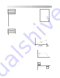
The effects of static and dynamic
friction are shown opposite.
Inertia Compensation
Many winders need inertia compensation
to add or subtract torque during
acceleration and deceleration to maintain
constant tension, especially at large roll
diameters. Without compensation, the
tension holding capability of open loop
winders diminishes during speed changes
causing tension sag.
The inertia compensation characteristics
is shown opposite.
For winder applications, inertia
compensation is split into two
components:
1.
Fixed inertia compensation for the
fixed motor, transmission and load
components.
2.
Variable inertia compensation for the
changing roll inertia. This is
especially necessary for high
diameter build unwinds and winders.
Tension & Comp
TENS+COMP [478]
–
0
INERTIA COMP O/P
[485]
–
0.00 %
0.00 %
–
[487] STATIC COMP
0.00 %
–
[488] DYNAMIC COMP
ENABLED
–
[489] REWIND
0.00 %
–
[479] FIX. INERTIA COMP
0.00 %
–
[480] VAR. INERTIA COMP
100.00 %
–
[481] ROLL WIDTH/MASS
0.00 %
–
[498] LINE SPEED SPT
10
–
[482] FILTER T.C.
10.00
–
[483] RATE CAL
0.00 %
–
[484] NORMALISED dv/dt
1.0000
–
[486] TENSION SCALER
MMI Menu Map
1
SETUP PARAMETERS
2
SPECIAL BLOCKS
3
TENS+COMP CALC.
STATIC COMP
DYNAMIC COMP
REWIND
FIX.INERTIA COMP
VAR.INERTIA COMP
ROLL WIDTH/MASS
LINE SPEED SPT
FILTER T.C.
RATE CAL
NORMALISED dv/dt
INERTIA COMP O/P
TENSION SCALER
MMI Menu Map
1
SYSTEM
2
CONFIGURE I/O
3
BLOCK DIAGRAM
TENS+COMP CALC.
Motor Speed
Static
Dynamic
Torque
(Armature Current)
Compensation
Compensation
Speed
Line Speed
100%
Time
deceleration
acceleration
Forward Torque
Time
large diameter roll
small diameter roll
(positive armature current)
Reverse Torque
(negative armature current)