


3-12
Installing the Converter
590+ Series DC Digital Converter
Power Connections
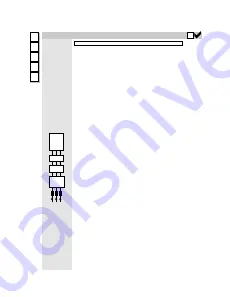
3-Phase Supply, 3-Phase External Contactor
L1
L2
L3
3
4
Connect the
main ac
power to
busbar
terminals L1,
L2 & L3 via
the Branch
Protection,
AC Filter
(optional),
3-Phase
External
Contactor,
and AC Line
Choke.
Connect the
contactor coil
to terminals 3
(Line) and 4
(Neutral).
Frame 3: Terminals 3 & 4 = D5 & D6 : Frame H: Terminals 3 & 4 = C & N
Main AC Power
There is no specific phase connection to terminals L1, L2 and L3 as the controller is
phase rotation independent.
Branch Protection
AC current = 0.83 x DC Armature Current
You must provide branch circuit protection using a suitable fuse or Type 2 circuit
breaker (RCD, ELCB, GFCI circuit breakers are not recommended, refer to “Earth Fault
Monitoring Systems”, page 3-28).
Also refer to Chapter 12: “Certification for the Converter” - Requirements for UL
Compliance.
Semi-Conductor Protection
Frame H drives contain high speed semi-conductor fuses. For all other frame sizes,
always provide high-speed thyristor fusing to protect the thyristor stack in the case of
direct output short circuits. Semiconductor fuses may be used as Branch Protection on
single-drive systems.
IMPORTANT:
If a motor becomes completely short-circuited, the current trip
(OVER I TRIP) will not protect the Converter.
Refer to Chapter 11: “Technical Specifications” - Power Semiconductor Protection
Fuses.
3-Phase External Contactor
The contactor does not switch current and is primarily for disconnection and sequencing
of the power bridge. It must be energised directly from the controller by a coil with a
rating suitable (AC1) for the controller concerned. No additional series contacts or
switches are permitted since they will interfere with the sequencing of the controller and
cause unreliability and possible failure.
Connect to main contactor terminals Con L
and Con N only as described in Chapter 11, otherwise unreliable or dangerous
operation may occur - do not connect to a PLC input or sensitive relay.
Slave Relay
: If the 3-phase contactor has a coil with an inrush greater than 3A, a slave
relay
MUST
be used to drive the contactor coil. The contactor and slave relay (if
required)
MUST
have coil voltages compatible with the controller auxiliary supply
voltage.
DO NOT use a slave relay with a coil current less than 25mA as it may be
energised by the contact suppression network.
Frames 4 & 5
: A relay jumper (CONN1) is provided on the power board enabling
terminals 3 & 4 to be powered (auxiliary supply - default position), or to be volt-free (for
customers own contactor supply). Refer to Chapter 13: “AH466701U001, U002, U003
(Frames 4 & 5)”.
DC Contactor
: A DC contactor can be used but the sequencing must be adjusted to
accomodate its use: an auxilliary normally open volt-free contact of the contactor must
be connected in series with the "ENABLE" input (C5) to disable the drive until after the
contactor is closed.
AC Line Choke
IMPORTANT:
Always fit the recommended choke. Refer to Chapter 11:
“Technical Specifications” - AC Line Choke.
We can provide suitable chokes, designed to connect directly to the drive terminals.
Refer to Chapter 11: "Technical Specifications" - AC Line Choke.
DRIVE
CHOKE
CON
FILTER
(optional)
Diagram
correct
of units
placement
shows