Description, device design, dimension drawing
2.6 Displays
PSU8600power supply systems
Manual, 04.2016, A5E35883207-7-76
29
2.6
Displays
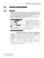
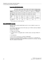
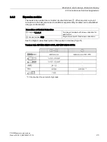
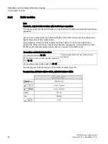
The operating state of the device and the operating state of the various outputs are
displayed using multi-color LEDs.
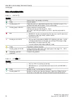
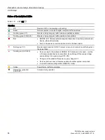
Meaning of the LEDs
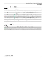
Symbols indicate the significance of each LED, which are listed in the following table.
Signaling
LED is off.
LED is continuously on
x
/
y
LED flashes in the interval
x
s on and
y
s off
2.6.1
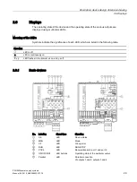
Basic devices
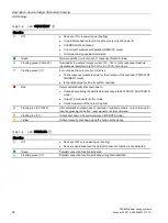
No. Labeling
Signal type
Signaling
①
OK
LED
Device status
②
MAN
LED
Mode
③
SF
LED
Group error
④
RUN
LED
RUN/STOP
⑤
P1/P2
LED
Receive/transmit, port 1 and port 2
⑥
ON/OFF/RST
LED buttons
Operating state of the particular output
⑦
Parallel
LED
Parallel connection
of outputs 1 and 2, outputs 3 and 4
Содержание SITOP BUF8600
Страница 6: ...Overview PSU8600power supply systems 6 Manual 04 2016 A5E35883207 7 76 ...
Страница 12: ...Safety instructions PSU8600power supply systems 12 Manual 04 2016 A5E35883207 7 76 ...
Страница 164: ...Engineering and remote access 7 4 SIMATIC STEP 7 PSU8600power supply systems 164 Manual 04 2016 A5E35883207 7 76 ...
Страница 240: ...Technical data 9 9 Dimension drawings PSU8600power supply systems 240 Manual 04 2016 A5E35883207 7 76 ...
Страница 246: ...Environmental conditions PSU8600power supply systems 246 Manual 04 2016 A5E35883207 7 76 ...
Страница 250: ...Environment PSU8600power supply systems 250 Manual 04 2016 A5E35883207 7 76 ...

