Description, device design, dimension drawing
2.5 Operator controls
PSU8600power supply systems
24
Manual, 04.2016, A5E35883207-7-76
2.4.3
Buffer modules
Note
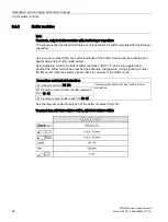
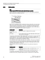
Terminals, only for buffer modules with double-layer capacitors
The subsequently described terminals are only available for buffer modules with double-layer
capacitors.
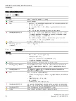
Using control contact (ON), the buffer readiness of the buffer module can be activated and
deactivated and/or buffer mode exited.
Using signaling contact "Sufficient buffer readiness" (RDY) it can be interrogated as to
whether the buffer module has reached an adequate charge state. Using signaling contact
"Buffer mode" (OK) the system signals that it is currently in the buffer mode.
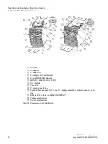
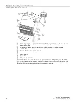
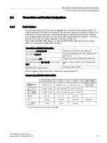
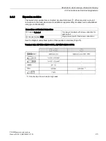
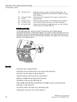
Connections and terminal designations
④
Control contact ON X1, X2
Common plug-in terminal, each with a screw
connection
⑤
Signaling contact "Sufficient buffer readiness"
RDY 13, 14
④
Signaling contact "Buffer mode" OK 23, 24
See the diagram under Description of the buffer modules (Page 16)
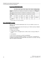
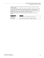
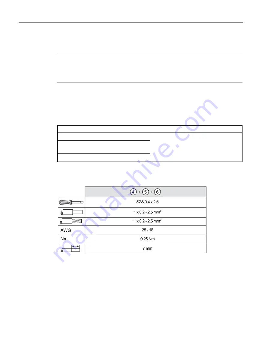
Terminal data 6EP4293-8HB00-0XY0, 6EP4295-8HB00-0XY0:
Содержание SITOP BUF8600
Страница 6: ...Overview PSU8600power supply systems 6 Manual 04 2016 A5E35883207 7 76 ...
Страница 12: ...Safety instructions PSU8600power supply systems 12 Manual 04 2016 A5E35883207 7 76 ...
Страница 164: ...Engineering and remote access 7 4 SIMATIC STEP 7 PSU8600power supply systems 164 Manual 04 2016 A5E35883207 7 76 ...
Страница 240: ...Technical data 9 9 Dimension drawings PSU8600power supply systems 240 Manual 04 2016 A5E35883207 7 76 ...
Страница 246: ...Environmental conditions PSU8600power supply systems 246 Manual 04 2016 A5E35883207 7 76 ...
Страница 250: ...Environment PSU8600power supply systems 250 Manual 04 2016 A5E35883207 7 76 ...

