SIPART DR20
Project Planning Manual
•
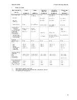
Option modules
Signal converter for
Order No.
Current
6DR2800-8J
Voltage
6DR2800-8J
Resistance
transmitter
6DR2800-8R
Resistance
thermometer
6DR2800-8P
Thermocouple,
mV
6DR2800-8T
Start-of-scale value
min. span
max. zero
supression
Full-scale value
0 / 4 mA
*)
20 mA
0 / 2 V
*)
or 199.6 mV
*)
10 V or 998 mV
0
Ω
∆
R
≥
0.8 R
R
A
≤
0.2 R
R = 80 to 1200
Ω
R
tA
≥
80.25
Ω
tA
≥
- 50
°
C
∆
R
t
= 19
Ω
R
tA
≤
5
∆
R
1
R
tE
≤
390.26
Ω
tE
≤
850
°
C
- 5
∆
U…0…+ 5
∆
U
∆
U = 10 mV
⏐
U
⏐
≤
5
∆
U
U
e
≤
60 mV
Input impedance
Difference
Common
mode
Permiss. Common-
mode voltage
Supply current
Line resistance
Two-wire
system
Three-wire
system
Four-wire
system
49.9
Ω
±
0.1 %
≥
500 k
Ω
0 to + 10 V
200 k
Ω
≥
200 k
Ω
0 to + 10 V
5 mA
±
5 %
<
10
Ω
each
100 mV /
∆
R
R
L1
+ R
L2
≤
10
Ω
R
L1
= R
L2
= R
L3
≤
50
Ω
R
L
≤
80
Ω
2 M
Ω
1 M
Ω
- 10 to + 10 V
R
L1
+ R
L2
≤
300
Ω
Filter time
Constant
±
20 %
50 ms
50 ms
50 ms
50 ms
20 ms
Error ***)
Zero
Gain
Linearity
Common-mode
Cold
junction
compensation
≤
0.3 %
≤
0.5 %
≤
0.05 %
≤
0.07 % / V
≤
0.2 %
≤
0.2 %
≤
0.05 %
≤
0.02 % / V
≤
0.2 %
≤
0.2 %
≤
0.2 %
≤
0.1 % **)
≤
0.1 % **)
≤
0.3 %
≤
0.1 % **)
≤
0.1 % **)
≤
0.1 %
≤
0.1 % / V
≤
2
°
C
Influencing effect of
temperature ***)
Zero
Gain
Cold junction
compensation
≤
0.05 % / 10 K
≤
0.1 % / 10 K
≤
0.02 % / 20 K
≤
0.1 % / 10 K
≤
0.1 % / 10 K
≤
0.3 % / 10 K
≤
0.2 % / 10 K
≤
0.3 % / 10 K
≤
0.3 % / 10 K
≤
0.3 % / 10 K
≤
0.5
°
C / 10 K
Stat. Destruction limit
across the inputs
Referred to M
Dyn. Destruct. limit
1.2/50
µ
s, 13 Ohm
±
40 mA
±
35 V
±
500 V
±
35 V
±
35 V
±
500 V
±
35 V
±
35 V
±
500 V
±
35 V
±
35 V
±
500 V
±
35 V
±
35 V
±
500 V
*)
Start-of-scale value by configuring
**)
Measuring ranges which can be marshaled or adjusted by the user
***)
Without error of A/D converter
67
Содержание SIPART DR20
Страница 1: ...s Compact Controller SIPART DR20 Project Planning Manual 02 05 Order No 6ZB5600 0AAO2 0BA0 ...
Страница 2: ...Project Planning Manual SIPART DR20 empty page 2 ...
Страница 82: ...Project Planning Manual SIPART DR20 SIPART Bus Fig 5 12 SES bus driver remote system wiring diagram 82 ...
Страница 111: ...SIPART DR20 Project Planning Manual Empty page 111 ...

