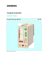
Project Planning Manual
SIPART DR20
The
standard controller
comprises :
•
a plastic housing with clamps for installation in switchboards, panels or machines
•
a front module latched into this housing
•
a basic circuit board which can be replaced towards the rear and which contains the output
stage for the K (continuous) or S (step) output and the power supply unit for various
operating voltages.
As already mentioned, a further four signal converter module can also be inserted into the rear of
the device (also during operation). The following are present:
•
two slots for analog inputs (AE3 and AE4)
•
one slot for alarm outputs with relays (A1/A2)
or
alarm and S outputs via four digital outputs with an additional input for blocking programming
inputs
•
one slot for a serial interface module
The mains connection is via a standardized plug for low-power appliances; a special plug is used
for a 24 V connection. All connections for field signals (except serial interface) consist of terminal
strips which can be inserted or removed for each circuit board as a complete block. This enables
prewiring and convenient replacement of modules or controllers. The terminal blocks have different
number of poles and mixing up in a controller is therefore impossible (except AE3 and AE4). All
additional modules are protected against incorrect insertion by mechanical coding of the circuit
boards. The slots are closed by covers if additional modules are not used.
3.1.1 Front
module
The front module consists of a plastic frame (material: Macrolon 8320), a printed, water-tight cover
foil (material: Mylar D), a replaceable scale with seals and a circuit board screwed to the frame.
The front module is latched into the housing and can only be removed using a special tool. Plug
connectors are arranged at the rear of the circuit board into which the basic circuit board and the
additional modules are inserted from the rear.
The front circuit board contains the display and control elements and the "intelligence" of the
device. LSI circuits enable a very small volume. The module contains:
•
the CPU
•
the non-erasable program memory
•
the non-volatile data memory for the parameters and configurations entered by the user
•
the time base
•
the data processing of the serial interface
•
the self-monitoring
•
the A/D and D/A conversion for all analog variables
•
the acquisition and output of digital signals
•
the acquisition of input functions and control of the display elements
14
Содержание SIPART DR20
Страница 1: ...s Compact Controller SIPART DR20 Project Planning Manual 02 05 Order No 6ZB5600 0AAO2 0BA0 ...
Страница 2: ...Project Planning Manual SIPART DR20 empty page 2 ...
Страница 82: ...Project Planning Manual SIPART DR20 SIPART Bus Fig 5 12 SES bus driver remote system wiring diagram 82 ...
Страница 111: ...SIPART DR20 Project Planning Manual Empty page 111 ...

