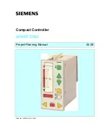
SIPART DR20
Project Planning Manual
All display elements are designed using LEDs thus ensuring a high service life and intensity and a
he controller has a very high number of different functions. All pushbuttons and displays are
d for
.1.2
Basic Circuit Board
he basic circuit board contains the power supply unit and the circuits required to match the field
a transformer power pack for the AC 115 V and AC 230 V designs, a primary switched-mode
•
internally required operating and reference voltages
f-scaIe
•
he function are
•
als. The direction of action and the function are
•
d variable signal output for 0/4 to 20 mA. The
or
/cooling)
aution:
The relays used are designed to carry a maximum switching voltage of 250 V
good viewing angle. The individual segments are driven in TDM mode. The control elements are
pushbuttons with a short travel, clear point of contact and high resetting force. They are activated
through the foil via a flexible switching board designed such that the foil cannot be over-stressed.
They are scanned in parallel mode by the processor and several pushbuttons can therefore be
activated simultaneously.
T
activated on the front module which are required for the specific function. Elements not require
a particular function have no effect.
3
T
signals of the standard controller to the microcontroller of the front module. This results in the
following function units:
•
power pack for the AC / DC 24 V design
a highly efficient voltage stabilizer for the
•
a short-circuit-proof voltage output of 20 V (L +) for transmitters or signal contacts
•
two current inputs of 0/4 to 20 mA into 249
Ω
without electrical isolation. The start-o
values and the functions can be programmed (see Section 3.2)
a digital input for 24 V logic signals. The direction of action and t
programmable (see Section 3.2)
a digital output for 24 V logic sign
programmable (see Section 3.2)
either
a continuous manipulate
start-of-scale value can be programmed
or
a switching output with two relays for 230 V / 5 A with a spark suppress
assembly, suitable for two-position controllers with two zones (e.g. heating
or as a three-position step controller for motorized actuators.
C
AC / DC 240 V phase-shift motors, that generate a resonance sharpness of
up to double the rated voltage on the open contact assembly, must therefore
only be driven by suitable separate switching elements !
15
Содержание SIPART DR20
Страница 1: ...s Compact Controller SIPART DR20 Project Planning Manual 02 05 Order No 6ZB5600 0AAO2 0BA0 ...
Страница 2: ...Project Planning Manual SIPART DR20 empty page 2 ...
Страница 82: ...Project Planning Manual SIPART DR20 SIPART Bus Fig 5 12 SES bus driver remote system wiring diagram 82 ...
Страница 111: ...SIPART DR20 Project Planning Manual Empty page 111 ...

