SIPART DR20
Project Planning Manual
•
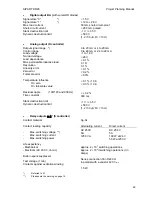
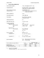
Serial interface (6DR2803-8A)
Communication signals
Transferable data
Communications procedure
Character format
Hamming distance d
Transmission speed
Transmission
Addressable stations
Data traffic watch-dog
Transmit output Txd
Signal level "0"
Point-to-point
Bus
Signal level "1"
Point-to-point
Bus
Receive input Rxd
Signal level "0"
Signal level "1"
*)
Electrical isolation
V.24 / V.28 signals to CCITT - V.24
Operational status, process variables,
parameters and configuring switches
to DIN 66258 A or B
10 bits (start bit, ASCII character with 7 bit,
parity bit and stop bit)
2 or 4
300 to 9600 bit/s
Asynchronous, half-duplex
Full-duplex for NAK
32
1 to 25 s or none
V.28
U
A
= + 5 to + 12 V
I
A
max. 1.67 mA
} short-circuit-
I
A
max. 15 mA
} proof
U
A
= - 5 to - 12 V
I
A
max. 1.67 mA
UA
≤
0 V
V.28
U
A
= 0 to + 35 V
I
E
= (U
E
- 0.7 V) / 6.8 k
Ω
U
A
= - 3 to - 35 V
I
E
= (U
E
+ 1.5 V) / 6.8 k
Ω
Txd:
without (referred to M (Ground))
Rxd:
by opto isolator
Recommended length
Cable capacitance and length at 9600 bit/s
Cable
capacitance
Unscreened
ribbon cable
Screened round
cable
V.28 point-to-point
≤
2.5 nF
50 m
10 m
SIPART Bus with bus driver
**)
≤
25 nF
500 m
100 m
TTY point-to-point with bus driver
**)
≤
75 nF
1500 m
300 m
*)
Signal level "1" is the rest position
**)
Bus driver C73451-A347-B202
An external power supply (
±
24 V, 100 mA) is required for the bus driver
69
Содержание SIPART DR20
Страница 1: ...s Compact Controller SIPART DR20 Project Planning Manual 02 05 Order No 6ZB5600 0AAO2 0BA0 ...
Страница 2: ...Project Planning Manual SIPART DR20 empty page 2 ...
Страница 82: ...Project Planning Manual SIPART DR20 SIPART Bus Fig 5 12 SES bus driver remote system wiring diagram 82 ...
Страница 111: ...SIPART DR20 Project Planning Manual Empty page 111 ...

