SIPART DR20
Project Planning Manual
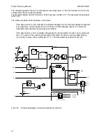
Switchover of the output, is as with the DDC controller. "Automatic mode" with the DDC manual
control station causes the manipulated variable to be held constant by the connection yA = y'.
(Details on the output structures are shown in Section 3.2.4).
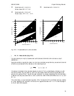
The four-digit display of the device can be used to indicate any process variable x1. The setpoint
output on the same display can be used in conjunction with the setpoint pushbuttons to display a
characteristic value.
This characteristic value and the process variable x1 are compared together and the result can be
read on the 21-part LED bargraph as the difference xd. x-tracking and wS following computer
failure must be switched off (S17 = 0, S18 = 0).
X1
INT
+
INT
gn
SP - w
w
i
w
w
w
a
w
e
T
w
0
0
0 0
S20, S21
Display
Key
8
8
8
8
8
8
8
4
+
-
SES
W
X
0
2
1
S23
A2
A1
a1
a2
Key
Key
8
8
8
8
8
8
8
13
S22
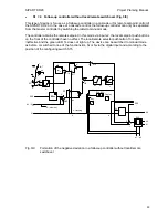
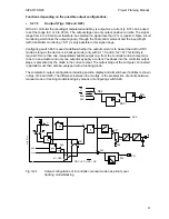
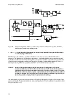
Fig. 3/18
Manual/automatic control station, DDC manual control station,
DDC manual control station, x and w display and alarm monitor
See Section 3.2.4 for diagrams of output circuit (page 46)
•
S1 = 10 Process indicator (Fig. 3/19)
The switchover configuration of the follow-up controller is used for signal processing. The four-digit
display either indicates a remote variable applied to input wE or a local value adjustable using the
setpoint pushbuttons as the setpoint w is depending on the position of the local/remote selector. If
an interface module is equipped, the remote setpoint wES received via the serial interface can also
be displayed.
41
Содержание SIPART DR20
Страница 1: ...s Compact Controller SIPART DR20 Project Planning Manual 02 05 Order No 6ZB5600 0AAO2 0BA0 ...
Страница 2: ...Project Planning Manual SIPART DR20 empty page 2 ...
Страница 82: ...Project Planning Manual SIPART DR20 SIPART Bus Fig 5 12 SES bus driver remote system wiring diagram 82 ...
Страница 111: ...SIPART DR20 Project Planning Manual Empty page 111 ...


