SIPART DR20
Project Planning Manual
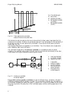
If a step function is applied to the controller input, then step responses corresponding to Fig. 1/2
are produced.
Characteristic values of the P controller are the proportional gain Kp and the working point yo. The
working point is defined as the value of the output signal at which the negative deviation becomes
zero.
In contrast to the P controller, a permanent deviation is avoided in the PI controller, irrespective of
the working point, the setting of the command variable and the variation in the disturbance
variables, by means of an integrating component. The characteristic value of the integrating
component is the reset time Tn.
The PID controller achieves an improvement of the dynamic control performance by the addition of
a D component. The D component is determined by the derivative action gain Vv and the
derivative action time Tv.
The controller output signals must be matched to the actuators. Two types of controllers are
common for the most important kinds of actuator:
Æ
three-position step controllers for electric actuators and
Æ
continuous controllers for pneumatic and hydraulic actuators
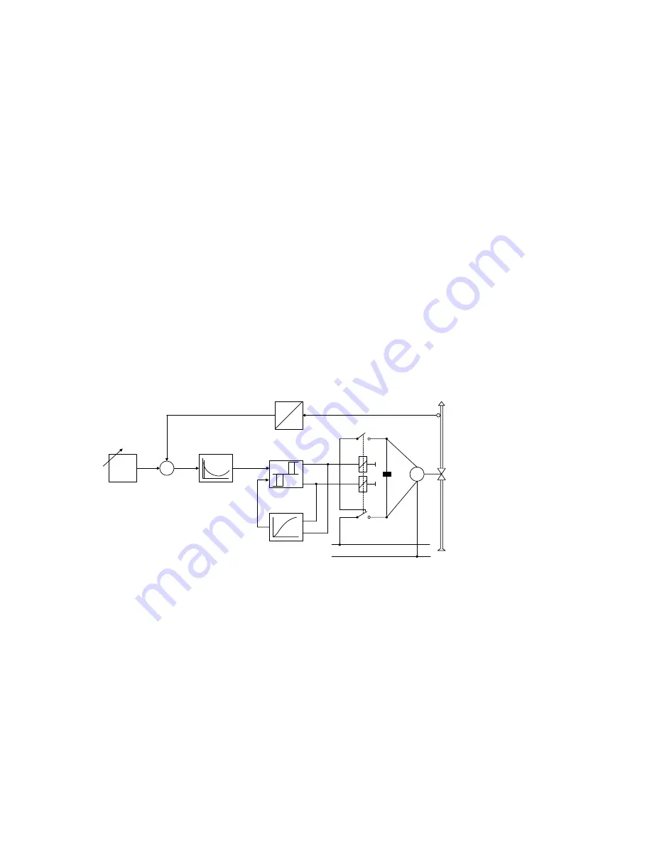
The three-position step controller switches the electric motor of the actuator to clockwise rotation,
stop or counterclockwise rotation by means of relays or semiconductor switches and can affect the
positioning speed of the final control element by means of different on/off ratios.
w
5
2
x
-
+
xd
3
1
y
x
4
M
L1
N
6
w Command
variable
x Controlled
variable
xd Negative
deviation
y Manipulated
variable
1 Transmitter
2 Setpoint
adjuster
3 Three-point
switch
4 Feedback
with
time response
5 Control
amplifier
6 Final
control
element
Fig 1/3
Three-position step controller, functional diagram
The switching performance of the three-point amplifier is reproduced in Fig 1/4 as a pulse diagram.
7
Содержание SIPART DR20
Страница 1: ...s Compact Controller SIPART DR20 Project Planning Manual 02 05 Order No 6ZB5600 0AAO2 0BA0 ...
Страница 2: ...Project Planning Manual SIPART DR20 empty page 2 ...
Страница 82: ...Project Planning Manual SIPART DR20 SIPART Bus Fig 5 12 SES bus driver remote system wiring diagram 82 ...
Страница 111: ...SIPART DR20 Project Planning Manual Empty page 111 ...

