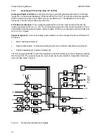
Project Planning Manual
SIPART DR20
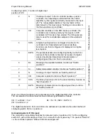
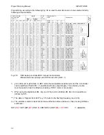
Configuring switch
position of S15
Function of digital input
2
N
Tracking of output. In the K controller and two- position
controller, the output stage is isolated from the control
algorithm by this signal and directly connected to the input
yN. The manipulated variable or the duty factor is then
determined by this input signal. Tracking is not possible in
the three-position step controller.
3
CB
Computer readiness. In the DDC backup controller, the
controller is set to backup mode by this signal, in SPC
controllers, SPC mode is then started. The CB signal can
also be used for controlled two-setpoint or three-setpoint
mode.
4
SES
A digital input signal does not trigger a function in the
controller but is transmitted via the serial interface.
Functions can then be triggered or displayed in a higher-
level system.
5
BLPS
The parameterization and configuring facility via the front
module of the controller is blocked by means of a digital
signal. Unauthorized adjustments to parameters or
configuring switches can then be prevented.
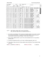
CB without acknowledg
ement
6
BL
Blocking of manipulated variable, function as "Switch
position 0”
7
Si
Safety manipulated variable, function as "Switch position 1"
8
N
Tracking of output, function as "Switch position 2"
9
CB
Computer enabled, function as "Switch position 3"
10
SES
The binary input only acts on the serial interface, function as
"Switch position 4"
11
BLPS
Blocking of parameters and configuring switches, function
as "Switch position 5"
CB with acknowledgement
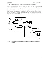
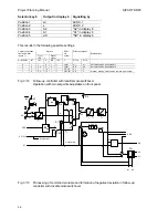
Only one of these functions can be processed via the digital input BE of the controller.
The non-selected functions therefore have defined signal states as follows:
CB = 1 with S42 = 0 or 1
BL = Si = N = SES = BLPS = 0
CB = 0 with S42 = 2
The digital functions BL, Si, N and CB can be addressed in parallel via the serial interface if
configuring switch S42 is in position 2.
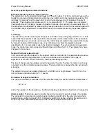
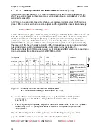
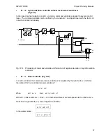
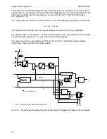
Acknowledgement of CB signal:
The controller is immediately switched to computer mode in positions 0 to 5 of the configuring
switch S15 with a CB switchover from 0 to 1 and with the front panel key 13 in position "Remote",
i.e. the controller operates "Without CB acknowledgement".
24
Содержание SIPART DR20
Страница 1: ...s Compact Controller SIPART DR20 Project Planning Manual 02 05 Order No 6ZB5600 0AAO2 0BA0 ...
Страница 2: ...Project Planning Manual SIPART DR20 empty page 2 ...
Страница 82: ...Project Planning Manual SIPART DR20 SIPART Bus Fig 5 12 SES bus driver remote system wiring diagram 82 ...
Страница 111: ...SIPART DR20 Project Planning Manual Empty page 111 ...


