Project Planning Manual
SIPART DR20
5. Mounting
5.1 Mechanical
Installation
Selection of mounting location:
The permissible ambient temperature range of 0 to 50 °C must not be violated, taking into
consideration heat sources in the environment. Note the possibility of heat accumulation in the
case of direct installation of devices one above the other. The front and rear of the controller must
be readily accessible.
Panel mounting:
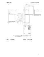
SIPART DR20 controllers are fitted either in individual panel cutouts or in open tiers (dimensional
drawing 4/2 on page 63).
-
In order to ensure adequate interference suppression, even at high frequencies, we
recommend that the paint be removed from the top edge of the panel cut-out. The contact
spring located on the top of the controller then produces a good HF earth connection.
-
Insert controller into panel cut-out or open tier from the front and attach the two clamps onto
the housing from the rear so that they latch into the housing cut-outs.
-
Align controller and tighten clamps. The clamp range is from 0 to 40 mm
5.2 Electric
Connection
Caution: The regulations for the installation of power systems with rated voltages below
1000 V must be observed (VDE 0100).
A protective earth connection has to be made and must not be disconnected,
while the controller is powered!
The arrangement of the connection elements is shown in Fig. 2/2 (page 12).
Protective earth connection:
The protective earth connection is made via grounding screw 6 at the rear. When connected to
115 V or 230 V power supplies, the protective earth connection can also be made via the mains
plug 7.
Power supply connection:
Power to the controller is supplied via a three-pin plug (IEC 320 V / DIN 49457 A) on 115 and
230 V AC systems, or by a special two-pole plug (polarity irrelevant) on 24 V AC/DC systems.
Power plugs are supplied with the controller.
Connect the lead via a switch and fuse (switch and fuse not included in scope of delivery). Check
the mains voltage specified on the rating plate of the device!
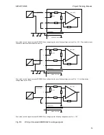
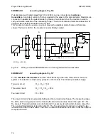
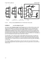
Connection of measuring and signal lines:
The standard controller K and S have 8-pin or 10-pin plug-in terminal blocks, the option modules
for analog inputs have 4-pin terminal blocks, those for alarm outputs have 5-pin terminal blocks.
70
Содержание SIPART DR20
Страница 1: ...s Compact Controller SIPART DR20 Project Planning Manual 02 05 Order No 6ZB5600 0AAO2 0BA0 ...
Страница 2: ...Project Planning Manual SIPART DR20 empty page 2 ...
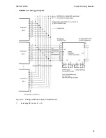
Страница 82: ...Project Planning Manual SIPART DR20 SIPART Bus Fig 5 12 SES bus driver remote system wiring diagram 82 ...
Страница 111: ...SIPART DR20 Project Planning Manual Empty page 111 ...

