SIPART DR20
Project Planning Manual
6.4 Lamp
Test
If pushbutton 8 is pressed for more than 5 s, all LEDs on the front panel of the controller light up
irrespective of the current display until the pushbutton is released again. The original display
setting is then reassumed.
6.5
Display of Software Release
In accordance with the technical developments of our products, the SIPART DR20 software is
matched to new knowledge as required. The software release is stored in a number (A..) in the
PROM and can be called as follows:
1.
U
N
= ----------------
∗
N + U
A
(N = 0 to 8)
8
2.
Press pushbutton 8 until lamp test is carried out. During the lamp test, press push-button 13. The
software release number appears in the four-digit display 4.
6.6
Further Information
Signalling of mains failure:
the four-digit display flashes when the controller is switched on or
following a power failure, or “- - - -“ flashes if the display is switched off (configuring switch
S21 = OFF). The display becomes continuous when acknowledged by key 8 (the basic setting w is
retained).
This signal should be observed! If parameterization or configuring was carried out immediately
before, it must be checked whether the new settings have already been transferred to the fail-safe
EEPROM (page 88). The controller can also start up with preset safety values depending on the
configuration selected using S41.
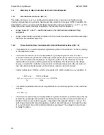
Setting of linearizer:
a non-linear physical controlled variable x1 must be linearized within its
measuring range prior to display. Linearization is carried out using a polygon curve consisting of 8
straight lines within the measuring range. The axis of the electric input variable x1
el
is divided into 8
identical intervals. The last straight-line equation is used further outside the measuring range.
The setting is described using the example of thermoelectric voltage linearization shown in
Fig. 6/2:
Divide the electric measuring range U
A
to U
E
(4.234 mV to 15.576 mV) into 8 identical
sections. Enter the partial voltages into a table (U
N
):
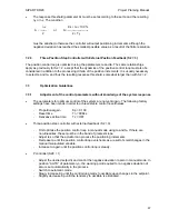
U
E
- U
A
Determine the associated temperature (t) for every U
N
from the DIN / IEC thermocouple table
and enter as parameters LA, L1 to L7, LE.
91
Содержание SIPART DR20
Страница 1: ...s Compact Controller SIPART DR20 Project Planning Manual 02 05 Order No 6ZB5600 0AAO2 0BA0 ...
Страница 2: ...Project Planning Manual SIPART DR20 empty page 2 ...
Страница 82: ...Project Planning Manual SIPART DR20 SIPART Bus Fig 5 12 SES bus driver remote system wiring diagram 82 ...
Страница 111: ...SIPART DR20 Project Planning Manual Empty page 111 ...

