SIPART DR20
Project Planning Manual
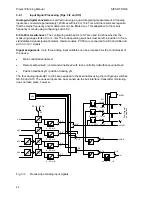
Transmitter monitoring:
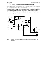
The measured values processed in this manner can be assigned to the monitoring circuit using
configuring switch S11. If one or more of the monitored variables violates the limits of -3 or
+103 %, the following is monitored on the four-digit display: "
1", "
2" or "
Y". This message
remains until acknowledged using the pushbutton 8 (Fig. 2/1). The value which was last displayed
then appears again. If several inputs are faulty simultaneously, all are monitored simultaneously.
As shown, all individual signals are “OR”-ed together in addition. The fault message "MuSt" can be
transmitted via the digital output or the serial interface. It is simultaneously available for
programmed switchover to manual mode.
Square-root extraction:
The position of configuring switches S12 and S13 determines whether the controlled variables x1
and x2/wE are square-rooted. Negative input values are not square-rooted; in this case the output
value is set to zero.
Linearization:
The main controlled variable x1 can be linearized if required; this is selected using configuring
switch S14. Linearization is carried out using a polygon characteristic with eight straight lines
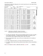
(see page 91 for setting and example).
The linearization circuit must always be used in the case of non-linear input values since
intermediate values can only be indicated correctly on the digital display in this manner. The
control response is also improved.
Digital input BE:
The controller has a digital input which acts normally (digital signal
≥
13 V = logical 1) or inverted
(digital signal
≤
4.5 V or open-circuit = logical 0) according to the position of configuring switch
S16. The function is assigned to the digital input by configuring switch S15 which has been
extended in software version A06 / A07:
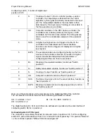
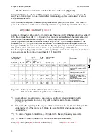
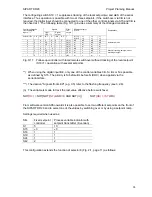
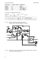
Configuring switch
position of S15
Function of digital input
0
BL
Blocking of manipulated variable. The last manipulated
variable current is retained in the K controller, the last duty
factor (heating or cooling output) is retained in the two-
position controller. A manipulated variable signal is no longer
output in the three-position step controller.
1
Si
Safety manipulated variable. The manipulated variable
assumes the parameterized safety value (yS) in the K
controller, two-position controller and three-position step
controller with external position feedback. In the three-
position step controller with internal simulation of the position,
the manipulated variable tends towards zero if the
parameterized safety value is less than 50 %, and towards
100 % if the parameterized safety value is equal to or greater
than 50 %.
CB without acknowledg
ement
23
Содержание SIPART DR20
Страница 1: ...s Compact Controller SIPART DR20 Project Planning Manual 02 05 Order No 6ZB5600 0AAO2 0BA0 ...
Страница 2: ...Project Planning Manual SIPART DR20 empty page 2 ...
Страница 82: ...Project Planning Manual SIPART DR20 SIPART Bus Fig 5 12 SES bus driver remote system wiring diagram 82 ...
Страница 111: ...SIPART DR20 Project Planning Manual Empty page 111 ...


