Project Planning Manual
SIPART DR20
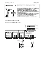
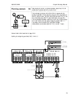
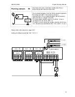
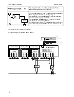
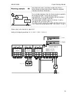
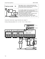
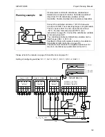
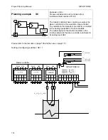
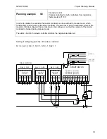
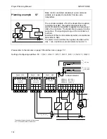
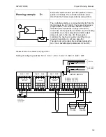
Planning example
S4
Fixed setpoint control, controlled variable direct from
thermocouple (external cold junction), position feedback
from electronic position transmitter (EPT)
W
X
y
Drive
Y
R
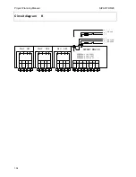
The controlled variable from the thermocouple is applied
to the analog input AE3. The measuring range is
programmable. The controlled variable must be linearized
(see instructions on pages 78 and 91).
The position feedback from the EPT is applied to input
AE2. The input signal range is 0 to 20 mA.
The alarm circuit monitors the controlled variable
(temperature) (set parameters A2 = min. and A1 = max.).
Please refer to the remarks on page 108 and the note on page 15 !
Setting of configuring switches: S2 = 2 or 3, S8 = 1, S14 = 1, S22 = 2, S32 = 1
AE1
AE2
BE
BA
L+
GND GND
L
1
2
3
4
5
6
7
8
SIPART DR20 S
6DR2001-1
(AC 230 V)
6DR2001-2
(AC 115 V)
6DR2001-4
(UC 24 V)
1
2
3
4
1
2
3
4
1
2
3
4
PE
N
L
AC 115 V
AC 230 V
⎫
⎬
⎭
PE
N
UC 24 V
L
⎫
⎬
⎭
Slot 3 GW
Slot 2 AE4
Slot 1 AE3
-
∆
y
+
∆
y
9
10
5
M1
A1
R1
A2
M2
not equipped
Option module
6DR2801-8A
M
M/A
S
E
L
N
+
-
Option module
6DR2800-8P
External cold
junction
EPT
+
-
+
-
R
comp
128
Содержание SIPART DR20
Страница 1: ...s Compact Controller SIPART DR20 Project Planning Manual 02 05 Order No 6ZB5600 0AAO2 0BA0 ...
Страница 2: ...Project Planning Manual SIPART DR20 empty page 2 ...
Страница 82: ...Project Planning Manual SIPART DR20 SIPART Bus Fig 5 12 SES bus driver remote system wiring diagram 82 ...
Страница 111: ...SIPART DR20 Project Planning Manual Empty page 111 ...

