SIPART DR20
Project Planning Manual
7. Commissioning
Most of the configuring switches and a number of parameters can already be set prior to actual
commissioning. Because of missing data and unclear relationships, the remaining ones can only
be determined in the system itself by "systematic trial-and-error". The following sections should be
of assistance:
7.1
Matching to Direction of Action
7.1.1
Matching the Direction of Action of the Controller to the Controlled System
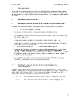
Definition of a normal-action system (including direction of action of final control element):
The controlled variable x increases
-
in continuous controllers with an increasing manipulated variable current Iy
-
in two-position controllers with an increasing duty factor of
∆
y and with a decreasing
duty factor of output -
∆
y
-
in three-position step controllers with manipulated variable signals of
∆
y
•
If the directions of action of the system and the final control element are known, configuring
switch S26 is set according to the table:
0
with a normal-action system,
1
with a reversed-action system.
•
If the directions of action of the system and the final control element are not known, set the
controller to manual mode (with S26 = 1): press the right-hand manipulated variable
pushbutton 5.2 briefly with the process switched off or in a safety position and observe whether
the controlled variable x rises or falls. A rising x means a normal-action system, a falling x
means a reversed-action system.
If closing of the final control element is detected during this test with three-position step
controllers, the ter
∆
y and -
∆
y must be interchanged.
7.1.2
Matching the Direction of Action of the Position Display to the
Controlled System
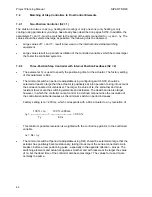
Configuring switch S33 is used to determine whether the manipulated variable signal y or the
position feedback yR are to be displayed directly or reversed (100 % - y or 100 % - yR). A normal-
action display is selected using S33 = 0 for a normal-action system (including final control
element). There are two possibilities for reversed-action systems:
-
S33 = 0
The manipulated variable increases with an increasing displayed value
-
S33 = 1
The controlled variable increases with an increasing displayed value
95
Содержание SIPART DR20
Страница 1: ...s Compact Controller SIPART DR20 Project Planning Manual 02 05 Order No 6ZB5600 0AAO2 0BA0 ...
Страница 2: ...Project Planning Manual SIPART DR20 empty page 2 ...
Страница 82: ...Project Planning Manual SIPART DR20 SIPART Bus Fig 5 12 SES bus driver remote system wiring diagram 82 ...
Страница 111: ...SIPART DR20 Project Planning Manual Empty page 111 ...

