


Project Planning Manual
SIPART DR20
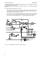
In the following, the defined (adjustable using the pushbuttons 12) ratio factor is referred to as the
setpoint ratio w
v
and indicated as the setpoint on the digital display. The range of adjustment of the
ratio factor v is defined by the parameters w
a
and w
e
within the limits 0.000 and 9.999 where
LA < w
a
and LE > w
e
.
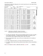
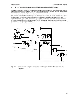
The current ratio is referred to as the actual ratio xv and is obtained by reversing the ratio formula:
x
v
= (x1 - c1) / x2
It is indicated as the actual value in the digital display and used for x-tracking if applicable.
The display range for ratio factors is 0.000 to 9.999 (negative values are suppressed) The negative
deviation display indicates xd = w - x as with the other controller types.
The setpoint ramp Tw is only effective at OFF or from 1 to 100 s. The alarm function enables
monitoring of the actual ratio or the setpoint ratio.
x1
INT
+
INT
gn
SP - w
w
vi
w
w
x2
w
va
w
ve
T
w
x1
0
0
0 0
S20 = 1, S21
Display
Key
88
8
8
8
8
8
4
W
Xd
0
2
1
S23
A2
A1
a1 a2
x2
x
v
=
x1 - c1
x2
x
v
S17
A
A
0
1
w
v
∗
x2 + c1 = w
+
-
X
+
-
S22
1)
1)
S22 = 0, effective starting with software version A09
x
v
- tracking
A =
H or N or Bl or Si
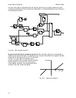
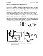
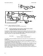
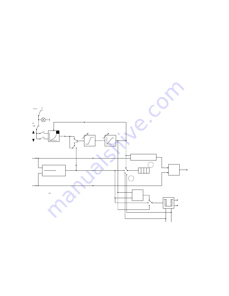
Fig. 3/15
Processing of command variable and formation of negative deviation in ratio controller
38
Содержание SIPART DR20
Страница 1: ...s Compact Controller SIPART DR20 Project Planning Manual 02 05 Order No 6ZB5600 0AAO2 0BA0 ...
Страница 2: ...Project Planning Manual SIPART DR20 empty page 2 ...
Страница 82: ...Project Planning Manual SIPART DR20 SIPART Bus Fig 5 12 SES bus driver remote system wiring diagram 82 ...
Страница 111: ...SIPART DR20 Project Planning Manual Empty page 111 ...