Project Planning Manual
SIPART DR20
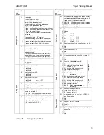
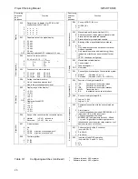
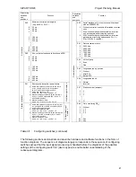
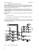
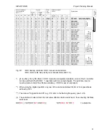
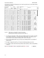
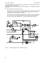
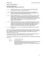
Programming according to the following Fig. 3/8 is used if automatic mode is to be selected directly
following computer failure.
Signals
Control commands
front and digital
inputs **)
Effec-
tive
output
Effective setpoint
S19=0
Front
LED ***)
Digital
output
Explanations
Com
p
u
ter
failure
H Si BL CB INT INT H
/RB /RC Y
S17=0
S18=0
=1
=0
=0
=1
=1
=1
0
0
0
1
0
0
0
0
0
yE(n) *)
wi
x
wS
wS
DDC mode
autom. mode prepared
1
0
0 1 0 0 1 1 1 yH(n)/ wi/ x
wi(n)/
x
Manual
mode
0
1
0 1 0 0 0,1
0 0 yS
wi
x
wi(n)
x
Safety
mode
1
1
0 1 0 0 0,5
1 1 yS
wi
x
wi(n)
x
Safety
mode
0
0
1 1 0 0 0,1
0 0 yBL wi
x
wi(n)
x
Blocking
mode
1
0
1 1 0 0 0,9
1 1 yH(n)/ wi/ x
wi(n)/
x
Manual
mode
0
1
1 1 0 0 0,1
0 0 yS
wi
x
wi(n)
x
Safety
mode
1
1
1 1 0 0 0,5
1 1 yS
wi
x
wi(n)
x
Safety
mode
Com
p
u
ter a
t
stan
dby
0
0
0 0 0 0,5
0 0 1 yA(n) wi
wi(n)
wi(n)
wi(n)
Automatic
mode
1
0
0 0 0 0,5
1 1 1 yH(n)/ wi
x
wi(n)/
x
Manual
mode
-
0
1
0 0 0 0,5
0,1
0 1 yS
wi
x
wi(n)
x
Safety
mode
1
1
0 0 0 0,5
0,5
1 1 yS
wi
x
wi(n)
x
Safety
mode
0
0
1 0 0 0,5
0,1
0 1 yBL wi
x
wi(n)
x
Blocking
mode
1
0
1 0 0 0,5
0,9
1 1 yH(n)/ wi
x
wi(n)/
x
Manual
mode
0
1
1 0 0 0,5
0,1
0 1 yS
wi
x
wi(n)
x
Safety
mode
1
1
1 0 0 0,5
0,5
1 1 yS
wi
x
wi(n)
x
Safety
mode
Com
p
u
ter
switched
off,
controller
at
DDC
backup standb
y
0
0
0 0 1 1 0 1 1 yA(n) wi/ wi(n)
wi(n)
wi(n)
Automatic
mode
1
0
0 0 1 1 1 1 1 yH(n)/ wi/ wi(n)
wi(n)/
wi(n)/
Manual
mode
0
1
0 0 1 1 0,1
1 1 yS
wi/ wi(n)
wi(n)
wi(n)
Safety
mode
1
1
0 0 1 1 0,5
1 1 yS
wi/ wi(n)
wi(n)
wi(n)
Safety
mode
0
0
1 0 1 1 0,1
1 1 yBL wi/ wi(n)
wi(n)
wi(n)
Blocking
mode
1
0
1 0 1 1 0,9
1 1 yH(n)/ wi/ wi(n)
wi(n)/
wi(n)/
Manual
mode
0
1
1 0 1 1 0,1
1 1 yS
wi/ wi(n)
wi(n)
wi(n)
Safety
mode
1
1
1 0 1 1 0,1
1 1 yS
wi/ wi(n)
wi(n)
wi(n)
Safety
mode
Com
p
u
ter
switched
off,
controller
n
o
t at
DDC ba
ckup
stan
dby
0
0
0 1 1 0,9
0 1 1 yA(n) wi/ wi(n)/
wi(n)/
wi(n)/
Automatic
mode
1
0
0 1 1 0,9
1 1 1 yH(n)/ wi/ wi(n)/ wi(n)/ wi(n)/ Manual
mode
0
1
0 1 1 0,9
0,1
1 1 yS
wi/ wi(n)/
wi(n)/
wi(n)/
Safety
mode
1
1
0 1 1 0,9
0,5
1 1 yS
wi/ wi(n)/
wi(n)/
wi(n)/
Safety
mode
0
0
1 1 1 0,9
0,1
1 1 yBL wi/ wi(n)/
wi(n)/
wi(n)/
Blocking
mode
1
0
1 1 1 0,9
0,9
1 1 yH(n)/ wi/ wi(n)/ wi(n)/ wi(n)/ Manual
mode
0
1
1 1 1 0,9
0,1
1 1 yS
wi/ wi(n)/
wi(n)/
wi(n)/
Safety
mode
1
1
1 1 1 0,9
0,5
1 1 yS
wi/ wi(n)/
wi(n)/
wi(n)/
Safety
mode
C
o
m
p
ut
e
r at
stan
dby,
controller
no
t a
t
DDC ba
ckup
stan
dby
Fig. 3/8
DDC backup controller/DDC manual control station
Manual mode has priority over DDC mode or BL (S29 = 1)
*) yE is either yN or yES (S42). In DDC mode the manipulated variable current of the K controller
can be switched off with S36 = 1 (operation with two output stages). The external y source
must be made to track the effective variable y, if DDC mode is not present.
**) When using the digital input BE, only one of the control variables CB, BL or Si is possible as
defined by S15.
***) The data on "Signals front LED" (e.g. 0.5) refer to the flashing frequency (see 3.2.6).
(n) The variable is made to track the last value effective before switchover, thus ensuring hitchless
switchover.
NOT(
RC
) = NOT{NOT(
INT
) AND
CB
AND NOT(
H
)} NOT(
RB
) =
INT
OR
H
/ = adjustable
32
Содержание SIPART DR20
Страница 1: ...s Compact Controller SIPART DR20 Project Planning Manual 02 05 Order No 6ZB5600 0AAO2 0BA0 ...
Страница 2: ...Project Planning Manual SIPART DR20 empty page 2 ...
Страница 82: ...Project Planning Manual SIPART DR20 SIPART Bus Fig 5 12 SES bus driver remote system wiring diagram 82 ...
Страница 111: ...SIPART DR20 Project Planning Manual Empty page 111 ...

