Project Planning Manual
SIPART DR20
Optional modules for alarm monitoring
Please refer to the note on signalling on page 27.
6DR2801-8A
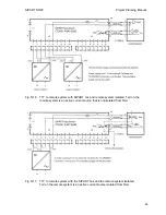
see connection diagram, Fig. 5/9
This module is equipped with two relays for external signalling of the alarms A1/A2. The contact
configuration can be set according to the connection diagram using soldered jumpers on the
module.
The RC combinations of the spark suppression elements are connected via the NO contacts when
delivered. The capacitors must be resoldered accordingly if the load is to be connected to the NC
contacts.
Consumers with a very low power may be influenced by the spark suppression capacitors (1
µ
F).
These must be replaced by smaller capacitors.
Only switching voltages up to AC/DC 35 V may be connected to the relay contacts!
6DR2801-8B
see connection diagram, Fig. 5/10
If this module is fitted for alarm monitoring, configuring switch S36 must be set to 1. The external
signalling of alarms is then made via the digital outputs A1/A2. With an S controller, the
manipulated variable signal is also output at the same time via this module (
±
∆
Y) and the output
relays in the standard controller are switched off. This module can be used to convert a K controller
into an S controller by setting configuring switch S2
≠
0.
The adjustment facility for parameter and configuring switch settings via the front panel keyboard is
suppressed by the additional digital input if this input (BLPS) is connected to 24 V (L+).
6DR2801-8A
22
75 V AC
3 / 4
a1
K1
K1
x11
x12
x13
a2
K2
x17
x14
x15
x16
3 / 5
22
75 V AC
3 / 2
x18
x19
3 / 3
3 / 1
1
µ
K2
A2
A1
x12 - x13
UC max. 35 V
3 / 4
3 / 5
3 / 2
3 / 3
3 / 1
A2
A1
x11 - x13
UC max. 35 V
3 / 4
3 / 5
3 / 2
3 / 3
3 / 1
Fig. 5/9
Connection diagram of module 6DR2801-8A for alarm monitoring
80
Содержание SIPART DR20
Страница 1: ...s Compact Controller SIPART DR20 Project Planning Manual 02 05 Order No 6ZB5600 0AAO2 0BA0 ...
Страница 2: ...Project Planning Manual SIPART DR20 empty page 2 ...
Страница 82: ...Project Planning Manual SIPART DR20 SIPART Bus Fig 5 12 SES bus driver remote system wiring diagram 82 ...
Страница 111: ...SIPART DR20 Project Planning Manual Empty page 111 ...

