


Project Planning Manual
SIPART DR20
3.2.7 Bus
Interface
Together with the module 6DR2803-8A/8C the SIPART DR20 can transmit and receive operating
states, process variables, parameters and configuring switch positions via a serial interface. Up to
32 controllers with these interface modules can be connected in parallel to a bus. Combination with
TELEPERM D devices is also permissible if the control of the higher-level computer permits this.
Data transmission is at a rate between 300 and 9600 bit/s set using configuring switch S42 and in
semi-duplex mode with asynchronous transmission of ASCII characters in a 10-bit frame (start bit,
ASCII character with 7 bits, parity bit and stop bit). The error message character NAK is
transmitted in full-duplex mode so that messages can be repeated rapidly in the event of a fault.
The controller is passive and only reacts when requested. The complete bus must be controlled by
the higher-level system (master/slave operation).
The configuring switches S42 to S48 are used to define the response of the serial interface and the
station numbers in the bus (between 0 and 31). These configuring switches can only be set
manually on the device and not via the interface itself.
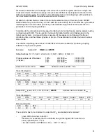
The transmission procedure (according to DIN 66258 A or B) commences with the start character
STX, followed by the station number, the data, the end character ETX and, if applicable, a cross-
check sum for additional data protection. The quantity of data to be transmitted, the start address
of a list range and a code for transmitting or receiving data are first defined in the data to be sent to
a controller. These are then followed, if applicable, by the data to be received. If the message is
received without faults, the SIPART DR20 replies immediately with a message with exactly the
same format: STX, station number, data, ETX and, if applicable, cross-check sum. The data
section is omitted because no values are requested.
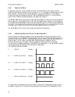
A particularly short procedure has been defined in addition in order to rapidly scan alarms and
other status signals from all stations connected to the bus:
Request:
STX, station number with code bit, ETX, cross-check sum
Reply:
STX, station number with reset bit, the two status bytes STN and STA,
ETX, cross-checksum
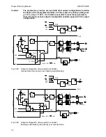
The serial interface is activated by configuring switch S42:
S42 = 0
The controller transmits all variables, i.e. parameters, configuring switches,
process variables and status signals, but does not receive any variables
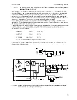
S42 = 1
The controller transmits all variables, but only receives parameters and the
configuring switch positions S1 to S41.
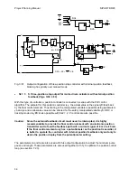
S42 = 2
The controller transmits all variables, and receives parameters, the configuring
positions S1 to S41 as well as wES, yES, STes (CB, N, Si, BL and BAes).
60
Содержание SIPART DR20
Страница 1: ...s Compact Controller SIPART DR20 Project Planning Manual 02 05 Order No 6ZB5600 0AAO2 0BA0 ...
Страница 2: ...Project Planning Manual SIPART DR20 empty page 2 ...
Страница 82: ...Project Planning Manual SIPART DR20 SIPART Bus Fig 5 12 SES bus driver remote system wiring diagram 82 ...
Страница 111: ...SIPART DR20 Project Planning Manual Empty page 111 ...