Project Planning Manual
SIPART DR20
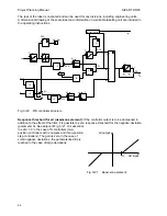
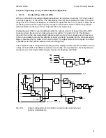
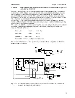
Priority switchover of manual and tracking mode/blocking:
It is possible to define the priority
for all controllers with internal position feedback using configuring switch S29.
S29 = 0
The digital functions N and BL have priority over manual switchover to
manual operation. An N or BL signal interrupts manual mode.
S29 = 1
Manual switchover has priority over the digital functions N and BL. If e.g. the
manipulated variable of a controller is blocked by the digital signal BL, direct
switching to manual mode is possible using the manual/automatic selector.
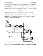
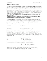
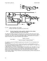
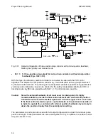
Manual manipulated variable yH:
The manual manipulated variable yH can only be adjusted in
manual mode using the pushbuttons 5.1 and 5.2. The adjustment is progressive in the K controller
and the S two-position controller. The adjustment is made every 0.1 s in steps which start with
0.1 %. The step size is increased linearly with time so that larger ranges of adjustment can also be
covered in a reasonable time. If the adjustment is interrupted, it can be started again with the
smallest rate of adjustment. An adjustment of the manipulated variable over the complete range
from 0 to 100 % Iasts approx. 5 s.
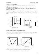
Positioning commands in three-position step controllers are simulated by manipulated variable
signals < 0 and > 100 % so that they act on the o
∆
y and -
∆
y like direct positioning
commands (continuous contact). All switchover functions and the minimum pulse lengths te and
pulse pauses ta remain effective, however.
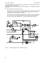
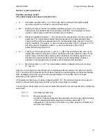
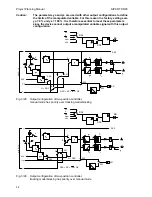
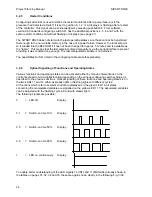
Position feedback yR:
A feedback via input yR must be made in three-position step controllers to
display the position of the final control element. This signal is used in the controller with external
position feedback (S2 = 3) for additional control of the position controller subordinate to the actual
controller. An electronic position transmitter (ESR) should always be used since this feedback must
not be interrupted. A resistance transmitter is sufficient in the case of S controllers with internal
position feedbacks (S2 = 2).
A position feedback is not required in K controllers if the following l/P position controller operates
linearly. If the manipulated variable current Iy is to be directly monitored nevertheless, the input yR
can also be used for this purpose providing it is not required for tracking purposes. Configuring
switch S32 must then be set to 1.
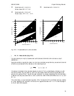
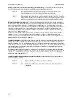
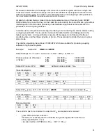
Position display and matching to direction of action:
Configuring switch S32 can be used to
select the display variable.
S32 = 0
y
(for K controllers and S two-position controllers)
S32 = 1
yR
(for three-position step controllers and K controllers with position
feedback)
48
Содержание SIPART DR20
Страница 1: ...s Compact Controller SIPART DR20 Project Planning Manual 02 05 Order No 6ZB5600 0AAO2 0BA0 ...
Страница 2: ...Project Planning Manual SIPART DR20 empty page 2 ...
Страница 82: ...Project Planning Manual SIPART DR20 SIPART Bus Fig 5 12 SES bus driver remote system wiring diagram 82 ...
Страница 111: ...SIPART DR20 Project Planning Manual Empty page 111 ...

