SIPART DR20
Project Planning Manual
All received information of a message is first stored in a receiver register with max. 32 byte and
checked for faults. Fault-free messages are processed further as input signals at the start of the
following arithmetic cycle. The transfer of modified parameter and configuring switch positions to
the non-volatile EEPROM requires several seconds, however.
All data to be transmitted are loaded into an intermediate memory at the end of each SIPART
DR20 arithmetic cycle so that they can be called if required during the next arithmetic cycle without
interfering with the internal data processing. Intermediate storage does not take place for the
parameters and configuring switches.
In addition to the comprehensive message monitoring, time monitoring can also be selected using
configuring switch S48. This is used to check whether data transfer is still taking place to the
higher-level system. A computer failure is assumed if messages do not follow within the set
monitoring time, and the CBes signal is set to zero. The associated controller then enters stand-
alone mode.
The interface operating instructions C73000-B7476-128 are available for producing coupling
software to higher-level systems.
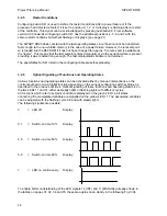
Example:
Setpoint W
READ
and
WRITE
Default settings: S1 = 5; S42 = 2; S43..46 = 0; S47 = StNr (= 0); S48 = 0
Process values are LIN-values:
100%:
LIN 8000
Hex
38 30 30 30
(
2
Bytes
)
50%
LIN
4000
Hex
34 30 30 30
25%
LIN
2000
Hex
32 30 30 30
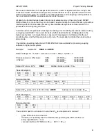
Setpoint W (value: 40%)
READ
Address inside controller: 72
Hex
Transmit-telegram:
STX
StNr
N1
Adr 1
Adr 2
ETX
02 40 61 37 32 03
Receive-telegram:
STX
StNr
Data 1 Data 2
Data 3
Data 4
ETX
02 40 33 33 33 32 03
Setpoint W
ES
(value: 40%
Æ
33 33 33 32)
WRITE
Address inside controller: 66
Hex
Transmit-telegram:
STX
StNr
N0
Adr 1
Adr 2
Data 1
Data 2
Data 3
Data 4
ETX
02 40 41
36 36 33 33 33 32 03
Receive-telegram:
STX
StNr
ETX
02
40
03
The controller has to be structured in order that W
ES
is accepted and monitored!
-
green LED above has to be OFF
therefore it is necessary that the controller has got the signal CB=1 whether via
binary input BE (S15 = 3) or
via serial interface ( STSES Adr. 65
Hex
; Bit7 = 1; 80
Hex
)
61
Содержание SIPART DR20
Страница 1: ...s Compact Controller SIPART DR20 Project Planning Manual 02 05 Order No 6ZB5600 0AAO2 0BA0 ...
Страница 2: ...Project Planning Manual SIPART DR20 empty page 2 ...
Страница 82: ...Project Planning Manual SIPART DR20 SIPART Bus Fig 5 12 SES bus driver remote system wiring diagram 82 ...
Страница 111: ...SIPART DR20 Project Planning Manual Empty page 111 ...

