


Closed-loop thyristor current control
System- and communication configuring D7-SYS - SIMADYN D
5-15
Edition 06.2002
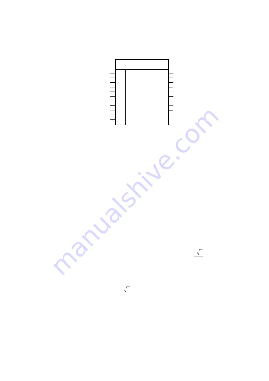
5.2.2 EMF, voltage - actual value sensing
Hardware address
Volt. sensing [V] Sitor
Motor volt. [V]
Normalization
Line voltage [V]
Offset frequency [kHz]
Armature resistance, normalized
Armature time constant [ms]
Smoothing time constant f. YEV [ms]
Current actual value
Handshake PC6
GV
R
R
R
R
R
R
TS
TS
R
BO
AD
RRV
ARV
NF
AAV
XFO
RA
TA
T
XC
ACI
EMF
YEM
YUA
YUR
YUL
YEV
YFU
YFO
TCC
ACO
QSF
R
R
R
R
R
R
R
TS
BO
W
Calculated EMF (actual value)
Output volt. – converter
Ohmic volt. drop
Inductive volt. drop
Calculated EMF, norm.
Frequency V/f conversion [kHz]
Offset actual value [kHz]
Integr. time voltage actual value
Handshake CAV
Fault
Fig. 5-8
EMF representation in the CFC
Using the function block FB EMF (Electro Motive Force), the actual
output voltage V
d
is determined and output at EMF.YUA.
The output voltage EMF.YUA is normalized using the system parameters
(EMF.RRV,.ARV,.NF) or is output as an absolute value.
The rated system voltage (e.g. rated motor voltage) should be specified
at input EMF.ARV; this is referred to the determined voltage values.
The induced voltage (EMF) of the motor is calculated taking into account
the ohmic and inductive voltage drop, dependent on current actual value
CAV.YC and is output at EMF.YEM.
The “Typical sensing voltage” of the SITOR set should be entered at
input EMF.RRV. SITOR sets 6QG2x/6QG3x are equipped as standard so
that the V/f converter frequency is increased by 30 kHz at the “Typical
voltage” (e.g. 6QG2\3 = 1000V).
The power section supply voltage should be entered at input EMF.AAV.
This is calculated from the no-load amplitude
π
2
3
13
⋅
L
V
.
ARV must be
>
0.675*AAV, otherwise the “Configuring error” error bit is
set at output QSF.
AAV
2
3
ARV
⋅
π
>
Function
Comments