


80
Operating Instructions – MOVIAXIS® MX Multi-Axis Servo Inverter
4
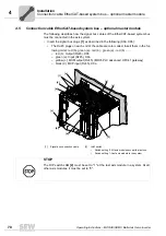
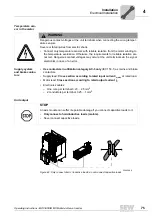
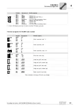
Wiring diagrams
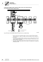
Installation
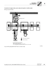
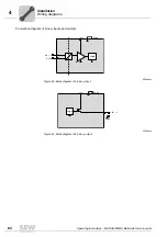
Connection of supply module, capacitor / buffer module, axis module, brake and
24 V switched-mode power supply module
62360AEN
Figure 46: Example: Wiring diagram MOVIAXIS
®
MX and brake, recommended wiring
L1 L2 L3
L1´ L2´ L3´
Line filter
K11
L1
L2
L3
PE
X1
1
2
3
L1 L2 L3
PE
X4
-
+
PE
1
2
Supply module
X3
-R
+R
PE
1
2
Affects
K11
X4
-
+
PE
Axis module
X6
2
1
X4
-
+
PE
Axis module
-
+
PE
Axis module
F16 *
1
2
1
2
1
2
X4
-
+
PE
Capacitor
module
1
2
Brake
control
**
X4
-
+
PE
24 V
Switched-
mode power
supply unit
1
2
X4
1)
1)
1)
1)
1)
1)
1)
X4 = DC link bar
Cable length < 600 mm
X2
Motor
1
2
3
PE U V W
Braking resistor
= PE (housing grounding point)
= Power shield clamp
PE
*
When F16 (trip contact at overload relay) triggers, K11 must be opened and DI00 "Output stage
enable" must receive a "0" signal. F16 is a signal contact, which means the resistor circuit must not
be interrupted.
**
Make sure to provide separate isolation for the brake lines when controlling the brakes with 24 V. We
recommend using SEW hybrid cables that offer complete shielding with shielding supports as well as
separate shielding for the brake line.
***
Install the connection cables between the brake rectifier and the brake separately from other power
cables when installing the brake rectifier in the control cabinet. Joint installation is only permitted with
shielded power cables.
Содержание MOVIAXIS MX
Страница 2: ...SEW EURODRIVE Driving the world...
Страница 210: ......
Страница 211: ...SEW EURODRIVE Driving the world...


