


68
Operating Instructions – MOVIAXIS® MX Multi-Axis Servo Inverter
4
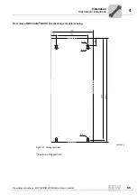
System bus connection cable for several axis systems – CAN-based
Installation
4.3
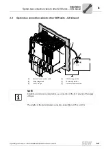
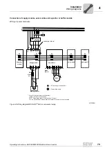
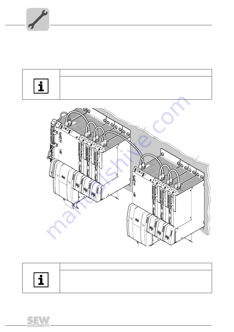
System bus connection cable for several axis systems – CAN-based
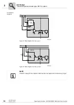
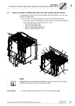
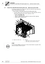
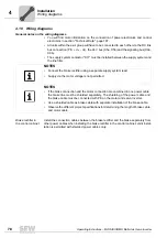
• The individual axis systems are connected as described on page 67.
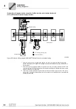
• The CAN connection cable
[1]
is routed from the red output (X9b) of the last axis
module in one axis system to the green input (X9a) of the first axis module of the sub-
sequent system.
The lengths of the pre-fabricated system bus connection cables
[1]
are 0.75 m and 3 m.
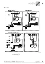
NOTE
The mounting plates on which the axis systems are mounted must have a sufficiently
large ground connection, e.g. a ground strap.
0
1
0
1
0
1
0
1
0
1
0
1
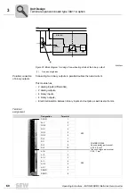
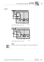
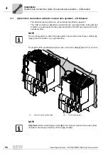
[1]
[2]
[1]
System bus connection cable
[2]
Terminating resistor
NOTE
Important:
Install a terminating resistor
[2]
in the last axis module of the axis system
(included in the scope of delivery of the supply module).
Содержание MOVIAXIS MX
Страница 2: ...SEW EURODRIVE Driving the world...
Страница 210: ......
Страница 211: ...SEW EURODRIVE Driving the world...


