


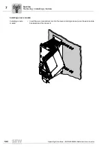


190
Operating Instructions – MOVIAXIS® MX Multi-Axis Servo Inverter
8
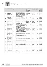
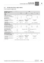
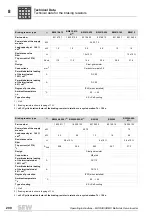
Technical data for the supply module
Technical Data
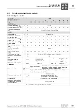
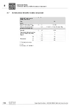
Control section supply module
GENERAL INFORMATION
Power loss at nominal capacity
W
30
80
160
280
No. of times power may be
switched on/off
min
-1
< 1/min
Minimum switch-off time for
mains off
s
> 10
Weight
kg
4.2
10.2
10.7
12.1
W
mm
90
90
150
Dimensions:
H
mm
300
400
D
mm
254
1) Nameplate information
2) Unit
3) In preparation
4) The output currents must be reduced by 20 % from the nominal values for V
mains
= 3
×
AC 500 V.
5) Decisive value for planning the assignment of supply and axis modules
6) Material strength [mm]
×
width [mm]
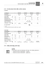
MOVIAXIS
®
supply module
MXP80A-...-503-00
1)
2)
Size
1
2
3
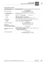
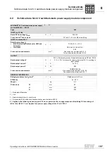
MOVIAXIS
®
MX supply module
General electronics data
CAN interface
1)
1) Only for CAN-based system bus
CAN
: 9-pin sub-D connector
CAN bus to CAN specification 2.0, parts A and
B, transmission technology to ISO 11898, max.
64 stations,
Terminating resistor (120
Ω
) has to be imple-
mented externally,
Baud rate can be set from 125 kBaud ...
1 MBaud,
expanded MOVILINK protocol,
see section 6.4 "Communication via CAN
adapter"
Cross section and contacts
DC 24 V voltage supply
DC 24 V ± 25 % (EN 61131)
COMBICON 5.08
One conductor per terminal: 0.20...2.5 mm
2
Two conductors per terminal: 0.25...1 mm
2
Decoupling of EtherCAT-based sys-
tem bus from 9-pin Sub D connector
DIP switch, 4-pole
Shield clamps
Shield clamps for control lines available
Maximum cable cross section that
can be connected to the shield clamp
10 mm (with sheath)
P
i
f
kVA
Hz
n
Содержание MOVIAXIS MX
Страница 2: ...SEW EURODRIVE Driving the world...
Страница 210: ......
Страница 211: ...SEW EURODRIVE Driving the world...


