


Operating Instructions – MOVIAXIS® MX Multi-Axis Servo Inverter
197
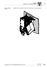
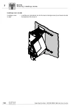
8
Technical data for 24 V switched-mode power supply module component
Technical Data
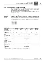
8.8
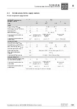
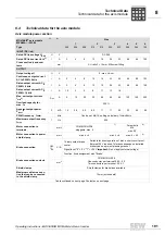
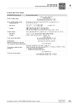
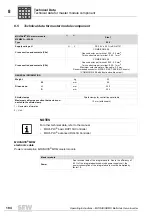
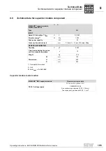
Technical data for 24 V switched-mode power supply module component
MOVIAXIS
®
24 V switched-mode power supply
module MXS80A-...-503-00
1)
2)
Type
060
INPUT via DC link
Rated DC link voltage U
NZK
U
V
DC 560
Cross section
3)
and contacts
CU rails 3
×
14 mm, M6 screw fitting
INPUT via external 24 V
Rated input voltage U
N
•
With direct control of brakes for CMP and
DS motors
•
Otherwise
U
V
DC-24 -0 % / +10 %
DC-24 ±25 % (EN 61131)
Cross section and contacts
mm
2
PC6
One conductor per terminal: 0.5...6
Two conductors per terminal: 0.5...6
OUTPUT
Rated output voltage V
U
V
DC 3 x 24 (shared ground). Tolerance for supply via DC link: DC 24
0 % / +10 %. Tolerance for supply via external 24 V: According to
input voltage
Rated output current I
I
A
3 x 10
4)
Rated output power P
P
W
600
Cross section and contacts
mm
2
COMBICON 5.08
One conductor per terminal: 0.20...2.5
Two conductors per terminal: 0.25...1
GENERAL INFORMATION
Bridging resistance for U
Z
drop
5)
t
s
Rated power for 10 ms
Efficiency
ca. 80 %
Weight
kg
4.3
Dimensions
W
mm
60
H
mm
300
D
mm
254
1) Nameplate information
2) Unit
3) Material strength [mm]
×
width [mm]
4) Not possible at the same time because total power is limited to 600 W
5) Applies to the following measuring point: 10 ms are guaranteed for an edge steepness of the falling DC link voltage of
(dU
ZK
/ dt) > (200 V / 1 ms). Applies for a power supply voltage U
ZK
of 3 x AC 380 V.
P
i
f
kVA
Hz
n
Содержание MOVIAXIS MX
Страница 2: ...SEW EURODRIVE Driving the world...
Страница 210: ......
Страница 211: ...SEW EURODRIVE Driving the world...


