


Operating Instructions – MOVIAXIS® MX Multi-Axis Servo Inverter
59
3
Terminal expansion board type XIA11A option
Unit Design
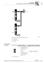
3.23 Terminal expansion board type XIA11A option
Supply
• The logic of the module is supplied by MOVIAXIS
®
.
• Analog inputs and outputs are also supplied by MOVIAXIS
®
.
• Binary inputs and outputs are supplied via the DCOM and 24 V terminals on the front.
The supply voltage must be protected with a 4 A fuse, see also page 99 in section
"UL compliant installation".
• The binary inputs and outputs are electrically isolated from the logic supply.
Module response
Short circuit
In the event of a short circuit of a binary output, the driver will change to pulse mode and
in this way protects itself. The status of the binary output does not change.
Once the short-circuit is eliminated, the status of the binary output is that which is output
by MOVIAXIS
®
at that point.
Switching inductive
loads
• The module does not contain an internal free-wheeling diode for receiving inductive
energies when inductive loads are switched off.
• The inductive load per output is 100 mJ at a frequency of 1 Hz.
• The inductive energy is converted into heat energy in the switching transistor. A volt-
age of -47 V is present. In this way, the energy can be reduced faster than by using
a free-wheeling diode.
• The load capacity of the outputs through inductive loads can be increased by adding
an external free-wheeling diode. However, switching off will take considerably
longer.
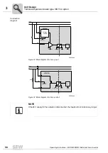
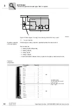
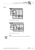
NOTE
For information on the ground designations used in the following diagrams, refer to sec.
"Terminal assignment" on page 89.
STOP
There is
no
electrical isolation
between servo drive and analog inputs and outputs on
the XIA card.
Содержание MOVIAXIS MX
Страница 2: ...SEW EURODRIVE Driving the world...
Страница 210: ......
Страница 211: ...SEW EURODRIVE Driving the world...


