Salicru CV30 Скачать руководство пользователя страница 20


20 - 140 

Installation Guidelines


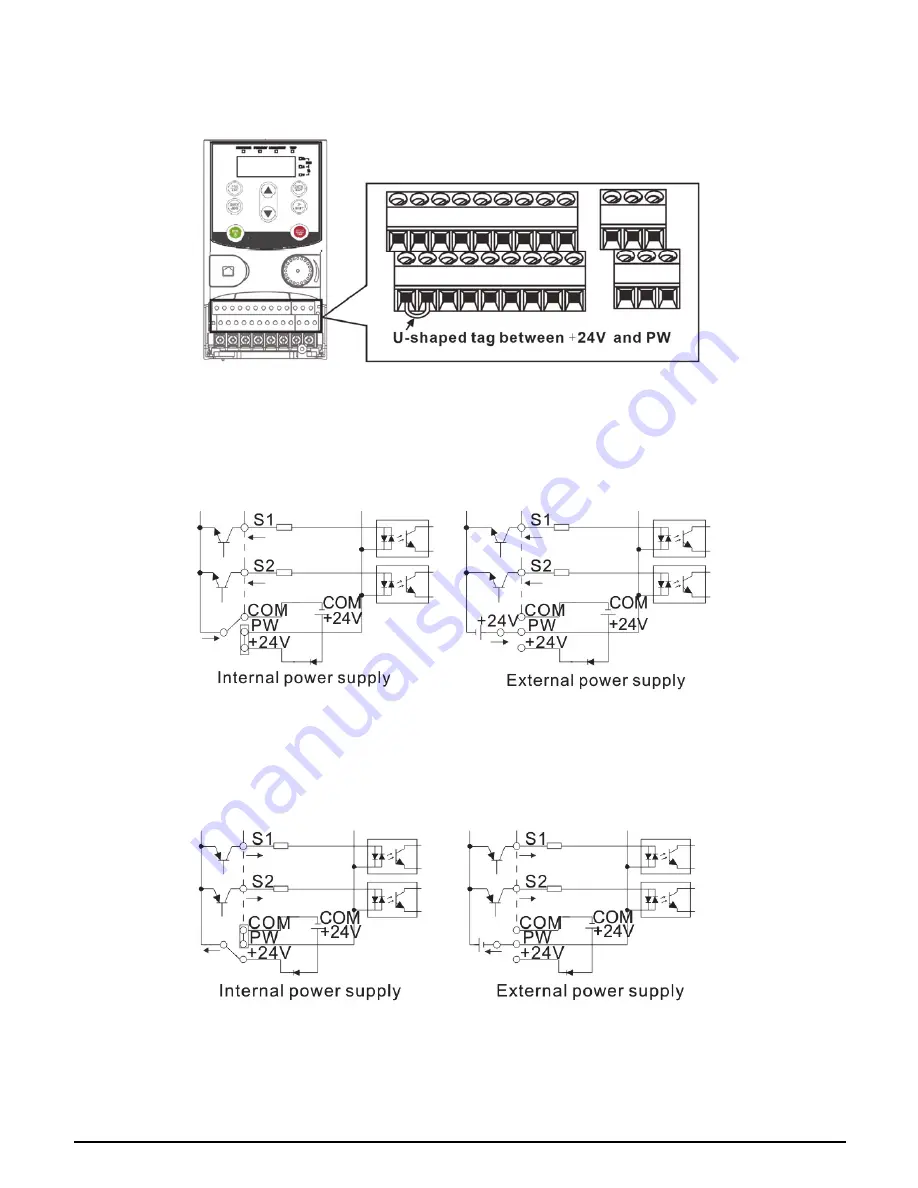
3.2.6 Input/Output signal connection figure   

Please use U-shaped contact tag to set NPN mode or PNP mode and the internal or external power supply. 
The default setting is NPN internal mode.   


Figure 3-11 U-shaped contact tag 


If the signal is from NPN transistor, please set the U-shaped contact tag b24V and PW as below 
according to the used power supply.   


Figure 3-12 NPN modes 


If the signal is from PNP transistor, please set the U-shaped contact tag as below according to the used 
power supply. 


Figure 3-13 PNP modes


Содержание CV30

Страница 1: ...USER MANUAL INVERTER CONTROLVIT CV30...

Страница 2: ......

Страница 3: ...90 6 1 Maintenance intervals 90 6 1 1 Cooling fan 92 6 1 2 Capacitors 93 6 1 3 Power cable 94 6 2 Fault solution 94 6 2 1 Alarm and fault indications 94 6 2 2 Fault reset 94 6 2 3 Fault instruction a...

Страница 4: ...e working on the device should take part in professional electrical and safety training receive the certification and be familiar with all steps and requirements of installing commissioning operating...

Страница 5: ...wiring diagram Do not operate on the inverter if there is any damage or components loss to the inverter Do not touch the inverter with wet items or body otherwise electric shock may occur Note Select...

Страница 6: ...zation see Maintenance and Hardware Fault Diagnose Cover the front board before running otherwise electric shock may occur 1 3 3 Maintenance and replacement of components Only qualified electricians a...

Страница 7: ...the power degree 2 Check that the actual current of the motor is less than the rated current of the inverter 3 Check that the control accuracy of the load is the same of the inverter 4 Check that the...

Страница 8: ...erminals are tightly fastened and the torque is appropriate 9 Check that there are no screws cables and other conductive items left in the inverter If not get them out 2 1 5 Basic commissioning Comple...

Страница 9: ...ing starting for running motor Peripheral interface Analog input 1 AI2 0 10V 0 20mA and 1 AI3 10 10V Analog output 2 AO1 AO2 0 10V 0 20mA Digital input 4 common inputs the Max frequency 1kHz 1 high sp...

Страница 10: ...pe designation contains information on the inverter The user can find the type designation on the type designation label attached to the inverter or the simple name plate CV30 040 4F Figure 2 2 Produc...

Страница 11: ...4 2 CV30 015 S2 1 5 15 7 7 5 CV30 022 S2 2 2 24 10 CV30 004 2 Three phase 220V 0 4 3 7 2 5 CV30 008 2 0 75 5 4 2 CV30 015 2F 1 5 7 7 7 5 CV30 022 2F 2 2 11 10 CV30 040 2F 4 17 16 CV30 055 2F 5 5 21 2...

Страница 12: ...runking board Protect the inner components and fix the cables of the main circuit 6 Name plate See Product Overview for detailed information 7 Potentiometer knob Refer to the Keypad Operation Procedur...

Страница 13: ...5 Name plate See Product Overview for detailed information 6 Cover for the heat emission hole Optional enhancement of the protective degree It is necessary to derate the inverter because the internal...

Страница 14: ...temperature 10 C 50 C and the temperature changing rate is less than 0 5 C minute If the ambient temperature of the inverter is above 40 C derate 1 for every additional 1 C It is not recommended to us...

Страница 15: ...ve materials and electrically conductive dust 3 1 2 Installation direction The inverter may be installed on the wall or in a cabinet The inverter needs to be installed in the vertical position Check t...

Страница 16: ...Standard wiring 3 2 1 Connection diagram of main circuit Figure 3 3 Connection diagram of main circuit Note The circuit breaker braking resistor input reactor input filter and output filters are opti...

Страница 17: ...input terminals which are generally connected with the power supply PB External dynamic braking resistor terminal Input terminal for DC bus U V W Three phase AC output terminals which are generally co...

Страница 18: ...W terminals and fasten 3 Connect the optional brake resistor with a shielded cable to the designated position by the same procedures in the previous step 4 Secure the cables outside the inverter mecha...

Страница 19: ...ower supply Max output current 50mA Used as the adjusting power supply of the external potentiometer Potentiometer resistance 5k above AI2 Analog input 1 Inputrange AI2voltageandcurrentcanbe chose 0 1...

Страница 20: ...ly The default setting is NPN internal mode Figure 3 11 U shaped contact tag If the signal is from NPN transistor please set the U shaped contact tag between 24V and PW as below according to the used...

Страница 21: ...verter is connected to multiple motors a separate thermal overload switch or a circuit breaker must be used for protecting each cable and motor These devices also may require a separated circuit break...

Страница 22: ...data and adjust parameters Figure 4 1 Film keypad Figure 4 2 External keypad Note 1 The film keypad is standard for the inverters of 1PH 230V 3PH 400V 2 2kW and 3PH 220V 0 75kW The external keypad is...

Страница 23: ...lt state LED off in normal state LED blinking means the inverter is in the pre alarm state 2 Unit LED Mean the unit displayed currently Hz Frequency unit RPM Rotating speed unit A Current unit Percent...

Страница 24: ...ternal keypad without the function of parameter copying is installed the local and external keypad LEDs are on 4 2 Keypad displaying The keypad displaying state of CV30 inverters is divided into stopp...

Страница 25: ...d the fault reset can be operated by the STOP RST on the keypad control terminals or communication commands 4 2 4 Displayed state of function codes editing In the state of stopping running or fault pr...

Страница 26: ...he password and the password protection becomes valid instantly after quitting from the function code editing state Press PRG ESC again to the function code editing state 0 0 0 0 0 will be displayed U...

Страница 27: ...Keypad Operation Procedure 27 140 Figure 4 5 Sketch map of state watching...

Страница 28: ...Terminals P06 Output Terminals P07 Human mafchine interface P08 Enhanced Function P09 PID Control P10 Simple PLC and Multi step speed control P11 Protective parameters P13 Control parameters of Short...

Страница 29: ...ter includes start stop forward reverse rotating jogging and fault reset 0 Keypad running command channel LOCAL REMOT light off Carry out the command control by RUN STOP RST on the keypad Set the mult...

Страница 30: ...quency 1 Analog AI1 setting corresponding to the keypad potentiometer 2 Analog AI2 setting corresponding terminal AI2 3 Analog AI3 setting corresponding terminal AI3 Set the frequency by analog input...

Страница 31: ...to 6 but the setting stage can only be the 1 15 stage The setting stage is 1 15 if P00 06 or P00 07 equals to 6 7 PID control setting The running mode of the inverter is process PID control when P00...

Страница 32: ...by P05 The factory default ACC DEC time of the inverter is the first group Setting range of P00 11 and P00 12 0 0 3600 0s Depend s on model P00 12 DEC time 1 Depend s on model P00 13 Running direction...

Страница 33: ...ncrease Applying low carrier frequency is contrary to the above too low carrier frequency will cause unstable running torque decreasing and surge The manufacturer has set a reasonable carrier frequenc...

Страница 34: ...tarting frequency after DC braking set the parameter P01 03 and P01 04 It is suitable in the cases where reverse rotation may occur due to the low inertia load during starting 2 Start after speed trac...

Страница 35: ...C braking is invalid The stronger the braking current the bigger the braking power The DC braking current before starting means the percentage of the rated current of the inverter The setting range of...

Страница 36: ...Starting frequency of DC braking Starting frequency of DC braking start the DC braking when running frequency reaches starting frequency determined by P1 09 Waiting time before DC braking Inverters b...

Страница 37: ...4 Switching between FWD REV rotation Set the threshold point of the inverter 0 Switch after zero frequency 1 Switch after the starting frequency 2 Switch after the speed reach P01 15 and delay for P01...

Страница 38: ...nitialization Note This function should be selected with caution or serious result may follow 0 P01 19 The running frequency is lower than the lower limit one valid if the lower limit frequency is abo...

Страница 39: ...r power off The function determines the waiting time before the automatic running of the inverter when powering off and then powering on Setting range 0 0 3600 0s valid when P01 21 1 1 0s P01 23 Start...

Страница 40: ...stator resistor 0 001 65 535 Depends onmodel P02 07 Motor rotor resistor 0 001 65 535 Depends onmodel P02 08 Motor leakage inductance 0 1 6553 5mH Depends onmodel P02 09 Motor mutual inductance 0 1 6...

Страница 41: ...rent of the motor Iout is the output current of the inverter and K is the motor protection coefficient So the bigger the value of K is the smaller the value of M is When M 116 the fault will be report...

Страница 42: ...cient is used to adjust the slip frequency of the vector control and improve the speed control accuracy of the system Adjusting the parameter properly can control the speed steady state error Setting...

Страница 43: ...upper limit frequency 3 Analog AI3 setting upper limit frequency 4 Pulse frequency HDI setting upper limit frequency 5 Multi step setting upper limit frequency 6 MODBUS communication setting upper li...

Страница 44: ...ne The usage of motor in weakening control Function code P03 22 and P03 23 are effective at constant power The motor will enter into the weakening state when the motor runs at rated speed Change the w...

Страница 45: ...by channel set by P04 27 to change the feature of the curve Note Vb in the below picture is the motor rated voltage and fb is the motor rated frequency 0 P04 01 Torque boost Torque boost to the outpu...

Страница 46: ...setting range of P04 05 P04 03 P04 07 The setting range of P04 07 P04 05 P02 02 rated motor voltage frequency 0 00Hz P04 04 V F voltage point 1 0 0 P04 05 V F frequency point 2 0 00Hz P04 06 V F volta...

Страница 47: ...put setting channel at V f curve separation 0 Keypad setting voltage The output voltage is determined by P04 28 1 AI1 setting voltage 2 AI2 setting voltage 3 AI3 setting voltage 4 HDI setting voltage...

Страница 48: ...I input selection 0 HDI is high pulse input See P05 49 P05 54 1 HDI is switch input same as S1 S4 terminals 0 P05 01 S1 terminals function selection Note S1 S4 and HDI are terminals on the control boa...

Страница 49: ...top at the current frequency 27 Traverse reset return to the center frequency 28 Counter reset 29 Torque control prohibition 30 ACC DEC prohibition 31 Counter trigger 32 Reserved 33 Cancel the frequen...

Страница 50: ...virtual terminal BIT3 S4 virtual terminal BIT4 S5 virtual terminal BIT5 S6 virtual terminal BIT6 S7 virtual terminal BIT7 S8 virtual terminal BIT8 HDI virtual terminal 0x000 P05 13 Terminals control r...

Страница 51: ...REV SIn is normal closed The direction control is as below during operation Sln REV Previous direction Current direction ON OFF ON Forward Reverse Reverse Forward ON ON OFF Reverse Forward Forward Rev...

Страница 52: ...ol terminal FWD REV keeps valid the inverter won t work when the stopping command is canceled Only when FWD REV is relaunched the inverter can start again For example the valid STOP RST stop when PLC...

Страница 53: ...is set by control terminal AI3 The function code defines the relationship between the analog input voltage and its corresponding set value If the analog input voltage is beyond the set minimum or max...

Страница 54: ...P05 38 100 0 100 0 The setting range of P05 39 P05 37 10 00V The setting range of P05 40 100 0 100 0 The setting range of P05 41 0 000s 10 000s The setting range of P05 42 10 00V P05 44 The setting r...

Страница 55: ...ration 4 Jogging operation 5 Inverter fault 6 Frequency degree test FDT1 7 Frequency degree test FDT2 8 Frequency arrival 9 Zero speed running 10 Upper limit frequency arrival 11 Lower limit frequency...

Страница 56: ...ime The function code defines the corresponding delay time of the electrical level change during the programmable terminal switching on and off The setting range 0 000 50 000s 0 000s P06 11 RO1 switch...

Страница 57: ...ion for detailed information Setting range of P06 17 100 0 P06 19 Setting range of P06 18 0 00V 10 00V Setting range of P06 19 P06 17 100 0 Setting range of P06 20 0 00V 10 00V Setting range of P06 21...

Страница 58: ...use it with caution P07 01 Parameter copy 0 No operation 1 Upload the local function parameters to the keypad 2 Download the keypad function parameters to the inverter including all the motor paramete...

Страница 59: ...yed parameters 1 of running state 0x0000 0xFFFF BIT0 running frequency Hz on BIT1 set frequency Hz flickering BIT2 bus voltage Hz on BIT3 output voltage V on BIT4 output current A on BIT5 running rota...

Страница 60: ...value V on BIT9 analog AI3 value V on BIT10 high speed pulse HDI frequency BIT11 PLC and the current stage of multi step speed BIT12 pulse counters BIT13 BIT15 reserved Example Default Value 0000 0000...

Страница 61: ...1000 Setting range of P07 16 0 0 999 9 kWh P07 16 Low bit of power consumption P07 17 Reserved Reserved P07 18 Rated power of the inverter 0 4 7 5 kW P07 19 Rated voltage of the inverter 50 440V P07...

Страница 62: ...ase loss 14 SPO Output side phase loss 15 OH1 Overheat of the rectifier module 16 OH2 Overheat fault of the inverter module 17 EF External fault 18 CE RS485 communication error 19 ItE Current detectio...

Страница 63: ...age at the current fault 0V P07 36 Output current at the current fault 0 0A P07 37 Bus voltage at current fault 0 0V P07 38 Max temperature at current fault 0 0 C P07 39 Input terminals state at curre...

Страница 64: ...ious 2 fault runnig frequency 0 00Hz P07 50 Ramp reference frequency at previous 2 faults 0 00Hz P07 51 Output voltage at previous 2 faults 0V P07 52 Output current at previous 2 faults 0 0A P07 53 Bu...

Страница 65: ...jogging DEC time means the time needed if the inverter goes from the Max Frequency P00 03 to 0Hz Setting range 0 0 3600 0s Depends on model P08 08 Jogging running DEC time Depends on model P08 09 Jum...

Страница 66: ...verse frequency the value which is relative to the sudden jumping frequency The raising time of the traverse frequency The time from the lowest point to the highest one The declining time of the trave...

Страница 67: ...d this set value the inverter will stop for the fault and wait to be repaired The interval time of the fault reset The interval between the time when the fault occurs and the time when the reset actio...

Страница 68: ...signal of frequency arrival see the diagram below for detailed information The setting range 0 00Hz P00 03 the Max frequency 0 00Hz P08 37 Energy Braking enable This parameter is used to control the i...

Страница 69: ...LED tens low speed carrier frequency limit mode 0 Low speed carrier frequency limit mode 1 the carrier frequency will limit to 1kHz or 2kHz if it exceeds 2kHz at low speed 1 Low speed carrier frequenc...

Страница 70: ...log potentiometer integral function 0 The Integral function is valid 1 The Integral function is invalid P08 43 Integral ratio of the keypad potentiometer 0 01 10 00s 0 10s P08 44 UP DOWN terminals con...

Страница 71: ...h P08 50 Magnetic flux braking coefficient This function code is used to enable magnetic flux 0 Invalid 100 150 the bigger the coefficient the stronger the braking strength The inverter can slow down...

Страница 72: ...step speed reference is realized by setting P10 group parameters 0 P09 01 Keypad PID preset When P09 00 0 set the parameter whose basic value is the feedback value of the system The setting range 100...

Страница 73: ...ring the proportional effect and differential effect to achieve the Max Frequency P00 03 or the Max Voltage P04 31 Shorter the integral time stronger is the adjustment If the value is reduced response...

Страница 74: ...ID 0 0 P09 11 Feedback offline detection value Set the PID feedback offline detection value when the detection value is smaller than or equal to the feedback offline detection value and the lasting ti...

Страница 75: ...hundreds P00 08 is 0 0 Limit to the maximum frequency 1 Limit to A frequency LED thousands 0 A B frequency buffer ACC DEC is invalid for the main reference A frequency source 1 A B frequency buffer AC...

Страница 76: ...0 to speed 15 When S1 S2 S3 S4 OFF the frequency input manner is selected via code P00 06 or P00 07 When all S1 S2 S3 S4 terminals aren t off it runs at multi step which takes precedence of keypad an...

Страница 77: ...7 100 0 100 0 Setting range of P10 2n 1 1 n 17 0 0 6553 5s min 0 0 P10 21 Running time of stage 9 0 0s P10 22 Multi step speed 10 0 0 P10 23 Running time of stage 10 0 0s P10 24 Multi step speed 11 0...

Страница 78: ...decimal bit and then set the corresponding function codes Setting range 0x0000 0xFFFF P10 36 PLC restart mode 0 Restart from the first stage Stop during running cause by the stop command fault or powe...

Страница 79: ...decreasing ratio at sudden power loss Setting range 0 00Hz s P00 03 the Max frequency After the power loss of the grid the bus voltage drops to the sudden frequency decreasing point the inverter begin...

Страница 80: ...If it exceeds the level the inverter will run at stable frequency in ACC running or the inverter will derate to run during the constant running If it exceeds the level continuously the output frequen...

Страница 81: ...erter continues to work after overload pre alarm and the inverter stops to run after underload fault 3 The inverter stops when overloading or underloading LED hundreds 0 Detection all the time 1 Detec...

Страница 82: ...10 0s 0 5s P11 16 Automatic frequency decreasing at voltage drop 0 Invalid 1 Valid ensure rated output torque when voltage drop 0x00 P13 Group Control parameters of Short circuit braking P13 13 Braki...

Страница 83: ...Baud rate Set the digital transmission speed between the upper monitor and the inverter 0 1200BPS 1 2400BPS 2 4800BPS 3 9600BPS 4 19200BPS 5 38400BPS Note The baud rate between the upper monitor and t...

Страница 84: ...function code is set as 0 0 the communication overtime parameter is invalid When the function code is set as non zero if the interval time between two communications exceeds the communication overtime...

Страница 85: ...t voltage Display current output voltage of the inverter Range 0 1200V 0V P17 04 Output current Display current output current of the inverter Range 0 0 5000 0A 0 0A P17 05 Motor speed Display the rot...

Страница 86: ...he percentage to the current rated torque of the motor Setting range 300 0 300 0 the rated current of the motor 0 0 P17 16 Linear speed Display the current linear speed of the inverter Range 0 65535 0...

Страница 87: ...ated motor current 0 0 P17 29 Reserved P17 30 Reserved P17 31 Reserved P17 32 Magnetic flux linkage Display the magnetic flux linkage of the motor Range 0 0 200 0 0 0 P17 33 Exciting current reference...

Страница 88: ...88 140 Fault Tracking Function code Name Detailed instruction of parameters Default value Modify P17 39 Reserved...

Страница 89: ...Function Parameters 89 140 5 2 Diagram of quick start...

Страница 90: ...ment by multimeter Conforming to the manual Keypad Ensure the display is clear enough Visual examination The characters are displayed normally Ensure the characters are displayed totally Visual examin...

Страница 91: ...sual examination NA Ensure that it is not offline Visual examination or measure with multimeter The resistors are in 10 of the standard value Transformers and reactors Ensure there is no abnormal vibr...

Страница 92: ...e The operating hours can be found through P07 14 accumulative hours of the inverter Fan failure can be predicted by the increasing noise from the fan bearings If the inverter is operated in a critica...

Страница 93: ...e for 30 minutes Add 50 rated voltage for 30 minutes Add 75 rated voltage for 30 minutes Add 100 rated voltage for 30 minutes Storing time more than 3 years Use power surge to charge for the inverter...

Страница 94: ...Alarm and fault indications Fault is indicated by LEDs See Operation Procedure When TRIP light is on an alarm or fault message on the panel display indicates abnormal inverter state Using the informa...

Страница 95: ...ooth 5 Check the output configuration 6 Check if there is strong interference 7 Check the setting of relative function codes OC2 Over current when deceleration OC3 Over current when constant speed run...

Страница 96: ...U V W phase loss or serious asymmetrical three phase of the load 1 Check the output distribution 2 Check the motor and cable OH1 Rectifier overheat 1 Air duct jam or fan damage 2 Ambient temperature i...

Страница 97: ...d frequency EEP EEPROM fault 1 Error of controlling the write and read of the parameters 2 Damage to EEPROM 1 Press STOP RST to reset 2 Change the main control panel PIDE PID feedback fault 1 PID feed...

Страница 98: ...inate the interference source Change hardware Backup data in the keypad again ETH1 Grounding shortcut fault 1 1 The output of the inverter is short circuited with the ground 2 There is fault in the cu...

Страница 99: ...ing certain device as the master is a promise other than setting by a bottom or a switch or the device has a special message format For example when the upper monitor is running if the operator clicks...

Страница 100: ...pairs When applying RS232 RS485 converter if the RS232 interface of the computer is connected to the RS232 interface of the converter the wire length should be as short as possible within the length...

Страница 101: ...ation frame format If the controller is set to communicate by RTU mode in Modbus network every 8bit byte in the message includes two 4Bit hex characters Compared with ACSII mode this mode can send mor...

Страница 102: ...ndard structure of RTU frame START T1 T2 T3 T4 transmission time of 3 5 bytes ADDR Communication address 0 247 decimal system 0 is the broadcast address CMD 03H read slave parameters 06H write slave p...

Страница 103: ...h is based on the CRC calculation method The CRC field is two bytes including 16 figure binary values It is added into the frame after calculated by transmitting device The receiving device recalculat...

Страница 104: ...me header is 0 3A frame end is CRLF 0 0D 0 0A by default In ASCII mode all the data bytes except for the frame header and frame end are transmitted in ASCII code mode in which four high bit groups wil...

Страница 105: ...mmand code 03H 03H correspond to binary 0000 0011 read N words Word the Max continuous reading is 16 words Command code 03H means that if the master read data from the inverter the reading number depe...

Страница 106: ...04H Data high bit of address 0004H 13H Data low bit of address 0004H 88H Data high bit of address 0005H 00H Data low bit of address 0005H 00H CRC CHK low bit 7EH CRC CHK high bit 9DH END T1 T2 T3 T4 T...

Страница 107: ...Low bit of data content 88H CRC CHK low bit C5H CRC CHK high bit 6EH END T1 T2 T3 T4 RTU slave response message from the inverter to the master START T1 T2 T3 T4 ADDR 02H CMD 06H High bit of writing...

Страница 108: ...high bit 14H END T1 T2 T3 T4 7 3 1 4 Command code 10H continuous writing Command code 10H means that if the master writes data to the inverter the data number depends on the data number in the comman...

Страница 109: ...Command code 03H 0000 0011 read N words Word max number for continuous reading is 16 words For instance As for the inverter whose slave address is 01H the starting address of internal storage is 0004...

Страница 110: ...e of this frame is listed as below ASCII master command message the command sent by the master to the inverter ASCII slave response message the message sent by the inverter to the master START START A...

Страница 111: ...B B LRC CHK Hi 3 LRC CHK Hi 3 LRC CHK Lo A LRC CHK Lo A END Hi CR END Hi CR END Lo LF END Lo LF 7 3 2 4 Command code 10H continuous writing function Command code 10H means the master write data to the...

Страница 112: ...ontrol the running of the inverter and get the state information and relative function parameters of the inverter 7 4 1 The rules of parameter address of the function codes The parameter address occup...

Страница 113: ...in RAM can set the address to 8007H This address can only be used in writing RAM other than reading If it is used to read it is an invalid address 7 4 2 The address instruction of other function in M...

Страница 114: ...d current of the motor W R 2009H Special control command word Bit0 1 00 motor Bit2 1 torque control prohibit 0 torque control prohibit invalid Bit3 1 power consumption clear 0 no power consumption cle...

Страница 115: ...ncy 3000H Range 0 00Hz P00 03 R Setting frequency 3001H Range 0 00Hz P00 03 R Bus voltage 3002H Range 0 2000V R Output voltage 3003H Range 0 1200V R Output current 3004H Range 0 0 3000 0 A R Operation...

Страница 116: ...annel And when operate on PID reference it is necessary to set P09 00 to MODBUS communication setting The encoding rules for device codes corresponds to identifying code 2103H of the inverter Code hig...

Страница 117: ...hibernation restore delay time if the response message of the inverter is as following Because the parameter data is 0032H 50 and 50 divided by 10 is 5 then the hibernation restore delay time is 5s 7...

Страница 118: ...on When the upper monitor is writing or reading and the user password is set without password unlocking it will report that the system is locked The slave uses functional code fields and fault address...

Страница 119: ...iting and reading Refer to section 7 3 for the command format 7 5 1 Example of reading command 03H Example 1 read the state word 1 of the inverter with the address of 01H refer to table 1 From the tab...

Страница 120: ...ASCII mode The command sent to the inverter If the response message is as below Example 2 set the Max Output frequency of the inverter with the address of 03H as100Hz See the figures behind the radix...

Страница 121: ...ress of communication setting frequency 2001H and 10Hz corresponds to 03E8H See the table below Function instruction Address definition Data meaning instruction R W characteristics Communication contr...

Страница 122: ...s and the DEC time as 20s P00 11 ACC time 1 Setting range of P00 11 and P00 12 0 0 3600 0s Depends on model P00 12 DEC time 1 Depends on model The corresponding address of P00 11 is 000B the ACC time...

Страница 123: ...on faults no response to the communication or the inverter returns abnormal fault The possible reason for no response to the communication Selecting wrong serial interface for example if the converter...

Страница 124: ...The function protects the input bridge of the drive against overload 2 The ratings apply at ambient temperature of 40 C 3 It is important to check that in common DC systems the power flowing through...

Страница 125: ...d voltage less than 1000 V other than pins sockets and motion devices and intended to be installed and commissioned only by a professional electrician when used in the first environment Note IEC EN 61...

Страница 126: ...ed in this manual 3 The drive is installed according to the instructions given in this manual A drive of category C3 is not intended to be used on a low voltage public network which supplies domestic...

Страница 127: ...e The external keypad is optional for the inverters 1PH 230V 3PH 400V 2 2kW and 3PH 220V 0 75kW the standard keypad of inverters 3PH 380V 4kW and 3PH 220V 1 5kW can be used as external keypad In both...

Страница 128: ...23 5 120 3 5 CV30 008 S2 80 0 60 0 160 0 150 0 123 5 120 3 5 CV30 015 S2 80 0 60 0 185 0 175 0 140 5 137 3 5 CV30 022 S2 80 0 60 0 185 0 175 0 140 5 137 3 5 CV30 004 2 80 0 60 0 185 0 175 0 140 5 137...

Страница 129: ...08 4 80 0 185 0 35 4 36 6 140 5 137 3 5 CV30 015 4 80 0 185 0 35 4 36 6 140 5 137 3 5 CV30 022 4 80 0 185 0 35 4 36 6 140 5 137 3 5 Wall mounting of 3PH 400V 4 7 5kW and 3PH 220V 1 5 7 5 kW inverters...

Страница 130: ...167 84 5 6 M5 CV30 022 2F 170 2 131 150 9 5 292 276 260 6 167 84 5 6 M5 CV30 040 2F 170 2 131 150 9 5 292 276 260 6 167 84 5 6 M5 CV30 055 2F 191 2 151 174 11 5 370 351 324 12 196 3 113 6 M5 CV30 075...

Страница 131: ...ow is the peripheral wiring of CV30 inverters Name Descriptions External keypad Including the external keypads with and without the function of parameter copying When the external keypad with the func...

Страница 132: ...nput of the inverter and placed under it Braking resistors Shorten the DEC time Choke Prolongues the effective transimitting distance of the inverter because controls the sudden high voltage provoqued...

Страница 133: ...ole drive system as well as motor bearing currents and wear Note A separate PE conductor is required if the conductivity of the cable shield is not sufficient for the purpose To function as a protecti...

Страница 134: ...e drive which cut down the testing voltage automatically Note Check the insulation of the input power cables according to local regulations before connecting the cables Model Recommended cable size mm...

Страница 135: ...escape from the breaker enclosure in case of a short circuit To ensure safe use special attention must be paid to the installation and placement of the breakers Follow the manufacturer s instructions...

Страница 136: ...nd 3PH 220V 1 5kW have an embedded C3 filter which can be disconnected by jumper J10 The input interference filter can decrease the interference of the inverter to the surrounding equipments SALICRU c...

Страница 137: ...re allowed to wire Damage to the inverter or braking options and part may occur Read carefully the instructions of braking resistors or units before connecting them with the inverter Do not connect th...

Страница 138: ...orque the braking resistor can be decreased properly and the power needs to be magnified Never use a brake resistor with a resistance below the minimum value specified for the particular drive The dri...

Страница 139: ......

Страница 140: ...22 05 services salicru com SALICRU COM The Technical Service and Support T S S network Commercial network and warranty information are available in website www salicru com Product Range Uninterruptib...

Отзывы: