129
When input phase loss protection is valid,
and input phase loss fault occurs, protection
action "E-12" will be enabled after a period of
time defined by FA.16, and the driver will coast
to stop.
FA.16
Delay time of input phase loss
protection
0.0S ~ 30.0s
1.0
When the VFD actual output current is higher
than rated current *【FA.17】, if output phase
loss protection is valid, action E-13 will be
enable after delay time of 5s and the driver
will coast to stop.
FA.17
Detection reference of output phase
loss protection
0%~ 100% *rated current of
VFD
50%
FA.18
Detection factor of output current
imbalance
1.00 ~ 10.00
1.00
if the ratio of the maximum value and
minimum value of three phase output current
is larger than this factor and last for over 10
seconds, the driver will display output current
imbalance fault E-13. When FA.08=1.00, output
current imbalance detection is invalid.
FA.23
reserved
reserved
0
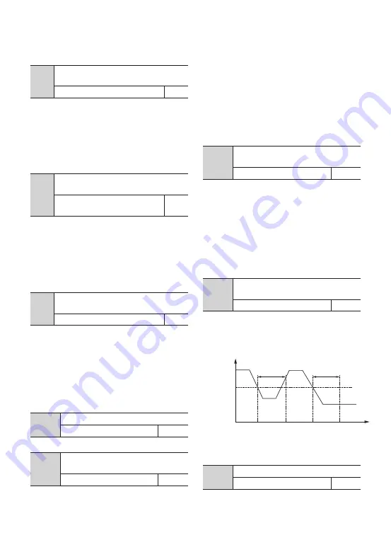
Fig. FA-4 Closed Loop
Feedback Loss Detection
FA.19
reserved
reserved
0
FA.20
PID feedback disconnection
processing
0 ~ 3
0
0: no action
1: alarm and run at frequency of disconnection
moment
2: protection action and coast to stop
3: alarm and decelerate to zero-speed running
according to set mode
FA.21
Feedback disconnection detection
value
0.0 ~ 100.0%
0.0%
The maximum value of PID input works as
the upper limit of feedback disconnection
detection value. Within the time of feedback
disconnection detection, when PID feedback is
lower than feedback disconnection detection
value continuously, the driver will respond
with corresponding protection action.
FA.22
Feedback disconnection detection
time
0.0 ~ 3600.0S
10.0
The lasting time before protection action after
feedback connection happened.
5JNF
$MPTFE-PPQ
'FFECBDL
%FUFDUJPO
7BMVF'"
-PTT
%FUFDUJPO
-PTT
%FUFDUJPO
-PTTOPU
%FUFDUJPO
'"
'"
4.2 Detailed Function Description
Содержание SKI600
Страница 3: ......
Страница 4: ...88888 Operating Instruction Manual High performance Vector Inverter ...
Страница 179: ......
Страница 180: ......


